Corrosion-resistant shell of high-low voltage switch cabinet

A high and low voltage switch, corrosion-resistant technology, applied in substation/switch layout details, substation/distribution device housing, measuring device, etc. Sex and other issues, to achieve the effect of a stable working area

Inactive Publication Date: 2021-11-19
江苏德鲁特电气设备有限公司
View PDF0 Cites 0 Cited by
  • Summary
  • Abstract
  • Description
  • Claims
  • Application Information

AI Technical Summary

Problems solved by technology

[0002] The working environment of the high and low voltage switchgear used outdoors is relatively harsh, especially in extreme weather conditions such as rain and snow, which will greatly affect the reliability of the high and low voltage switchgear. When the high and low voltage switchgear is in It is inevitable to bear certain safety risks when working, so it is of practical significance to develop a corrosion-resistant housing for high and low voltage switchgear that is corrosion-resistant in acid-alkaline environments and provides a stable working range.

Method used


Image

  • Corrosion-resistant shell of high-low voltage switch cabinet
  • Corrosion-resistant shell of high-low voltage switch cabinet
  • Corrosion-resistant shell of high-low voltage switch cabinet

Examples


Embodiment 1

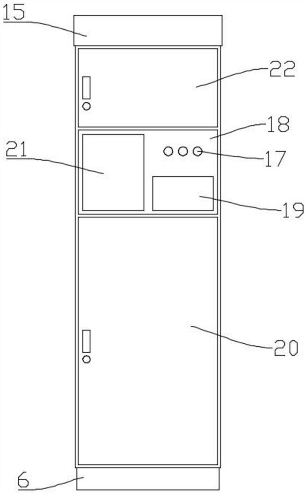
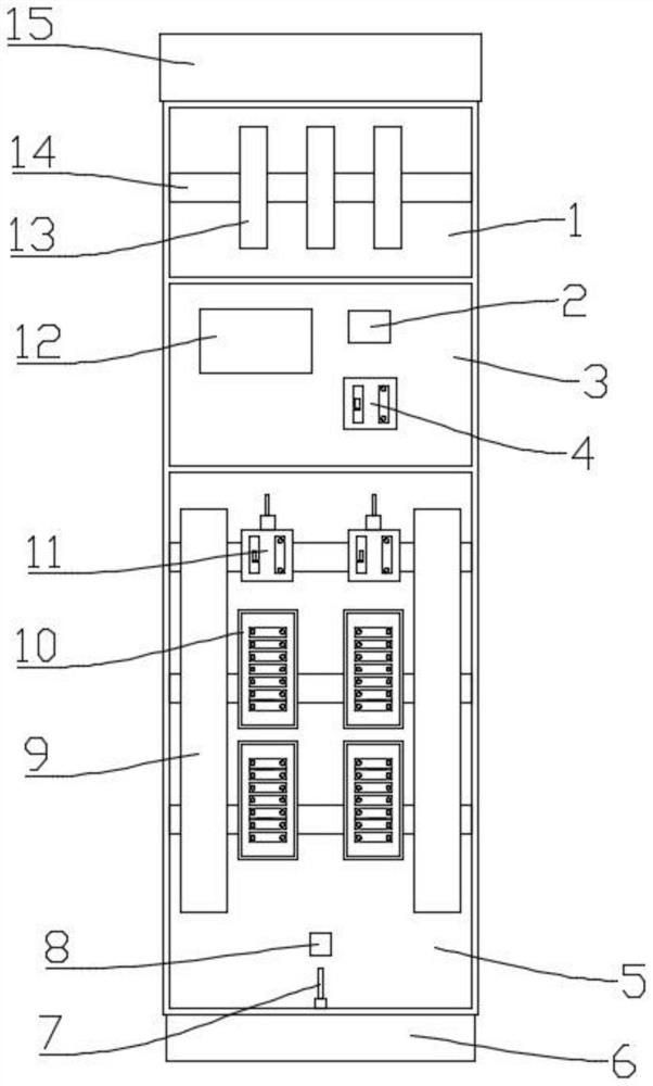
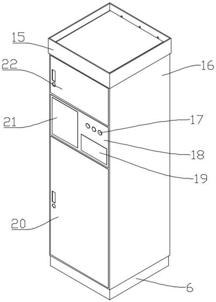
[0027] like Figure 1~6 As shown, a corrosion-resistant shell of a high and low voltage switchgear, a power converter 2, a main switch 4, a base 6, an electrode 7, a Hall sensor 8, two flame-retardant wire slots 9, two shunt switches 11, PLC controller 12, three copper plates 13, four installation beams 14, upper cover plate 15, cabinet body 16, three indicator lights 17, second panel 18, nameplate 19, third panel 20, operation panel 21, first panel 22, three connectors 23, three conduits 24 and four shunt fuse banks 10;

[0028] The upper part of the upper cover 15 is provided with a sump 151, the lower part of the lower cover is provided with an embedding groove 153, and the side wall of the upper cover 15 is provided with three water outlets 154, and the three outlets 154 are all communicated with the sump 151;

[0029] The upper panel 152 of the upper cover 15 is in the shape of an upward convex platform, and the water collected in the sump 151 can be collected along the ...

Embodiment 2

[0040] like Figure 7-12 As shown, a corrosion-resistant shell of a high and low voltage switchgear, a power converter 2, a main switch 4, a base 6, an electrode 7, a Hall sensor 8, two flame-retardant wire slots 9, two shunt switches 11, PLC controller 12, three copper plates 13, four installation beams 14, upper cover plate 15, cabinet body 16, three indicator lights 17, second panel 18, nameplate 19, third panel 20, operation panel 21, first panel 22, three connectors 23, three conduits 24 and four branch circuit breaker groups 25;

[0041] The upper part of the upper cover 15 is provided with a sump 151, the lower part of the lower cover is provided with an embedding groove 153, and the side wall of the upper cover 15 is provided with three water outlets 154, and the three outlets 154 are all communicated with the sump 151;

[0042] The upper panel 152 of the upper cover 15 is in the shape of a slope, and the water collected in the sump 151 can be collected along the uppe...


PUM


Abstract

The invention discloses a corrosion-resistant shell of a high-low voltage switch cabinet. The shell comprises a power converter (2), a main switch (4), a base (6), an electrode (7), a Hall sensor (8), a flame-retardant wire slot (9), a shunt switch (11), a PLC (Programmable Logic Controller) (12), a copper plate (13), a mounting beam (14), an upper cover plate (15), a cabinet body (16), an indicator lamp (17), a second panel (18), a nameplate (19), a third panel (20), an operation panel (21), a first panel (22), a connecting piece (23), a conduit (24) and a power distribution component. The upper part of the upper cover plate (15) is provided with a water collecting tank (151), the lower part of the lower cover plate is provided with an embedding groove (153), the side wall of the upper cover plate (15) is provided with a water outlet (154), and the water outlet (154) is communicated with the water collecting tank (151). The corrosion-resistant shell has the advantages of corrosion resistance in an acid-base environment, capability of providing a relatively stable working interval and the like, and can be widely applied to the field of electrical engineering.

Description

technical field [0001] The invention relates to the field of electrical engineering, in particular to a corrosion-resistant shell of a high and low voltage switchgear. Background technique [0002] The working environment of the high and low voltage switchgear used outdoors is relatively harsh, especially in extreme weather conditions such as rain and snow, which will greatly affect the reliability of the high and low voltage switchgear. When the high and low voltage switchgear is in It is inevitable to bear certain safety risks during work, so it is of practical significance to develop a corrosion-resistant housing for high and low voltage switchgear that is corrosion-resistant in acid-base environments and provides a stable working range. Contents of the invention [0003] In order to solve the above technical problems, the present invention discloses a corrosion-resistant casing of a high and low voltage switchgear, a power converter, a main switch, a base, electrodes, ...

Claims


Application Information

Patent Timeline
Patent Type & Authority Applications(China)
IPC IPC(8): H02B1/30H02B1/38H02B1/28G01R31/00
CPCH02B1/30H02B1/38H02B1/28G01R31/00
Inventor 袁坤
Owner 江苏德鲁特电气设备有限公司
Why Eureka
Try Eureka