Eureka AIR delivers breakthrough ideas for toughest innovation challenges, trusted by R&D personnel around the world.

Automatic heat dissipation distribution box

A distribution box, automatic technology, applied in the direction of photovoltaic power generation, electrical components, substation/switch layout details, etc., can solve the problems of inability to adjust power, increase the cost of use of distribution boxes, and loss of service life of components, so as to reduce the use of Cost, better heat dissipation, and increased cooling efficiency

Pending Publication Date: 2021-11-19
ANHUI POLYTECHNIC UNIV MECHANICAL & ELECTRICAL COLLEGE
View PDF0 Cites 6 Cited by
  • Summary
  • Abstract
  • Description
  • Claims
  • Application Information

AI Technical Summary

Problems solved by technology

Among them, if it is installed outdoors, especially in summer when the ambient temperature is high, the electronic components, instruments, switches and lines in the distribution box will be under the test of high temperature for a long time, and the service life of the internal lines and components will be accelerated. It is easy to cause line failure, so there are usually heat dissipation devices inside, but these heat dissipation devices cannot make corresponding power adjustments according to the ambient temperature, which will increase the use cost of the distribution box during use

Method used


Image

  • Automatic heat dissipation distribution box
  • Automatic heat dissipation distribution box
  • Automatic heat dissipation distribution box

Examples


Embodiment Construction

[0031] The technical solutions in the embodiments of the present invention will be clearly and completely described below with reference to the accompanying drawings in the embodiments of the present invention. Obviously, the described embodiments are only a part of the embodiments of the present invention, but not all of the embodiments. Based on the embodiments of the present invention, all other embodiments obtained by those of ordinary skill in the art without creative efforts shall fall within the protection scope of the present invention.

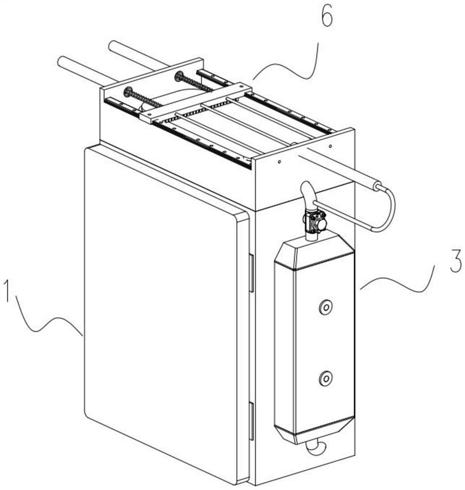
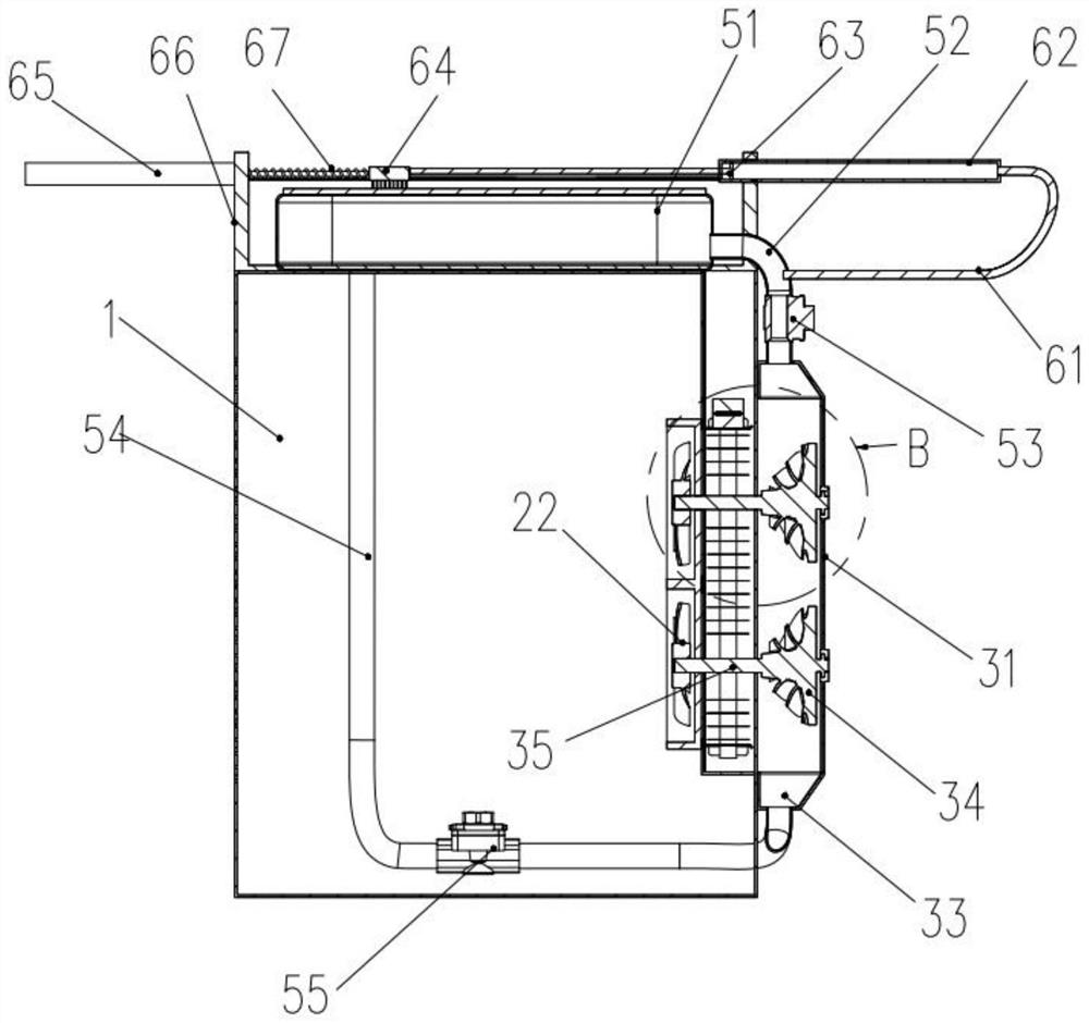
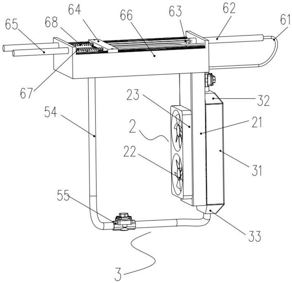
[0032] see Figure 1 to Figure 8 , the present invention provides a technical solution: an automatic heat dissipation power distribution box, including a power distribution box 1, a cooling fan device 2 and a hot air drive device 3 are arranged on the side wall of the power distribution box 1, and the cooling fan A refrigeration assembly 4 is arranged between the device 2 and the hot air driving device 3, and a heat collecting device ...


PUM


Abstract

The invention discloses an automatic heat dissipation distribution box, which relates to the field of distribution box heat dissipation equipment. The automatic heat dissipation distribution box comprises a mobile base and a distribution box, the side wall of the distribution box is provided with a heat dissipation fan device and a hot air driving device, a refrigeration assembly is arranged between the heat dissipation fan device and the hot air driving device, and the top of the distribution box is provided with a heat collecting device. The heat collecting device is used for absorbing external heat, heating air in the heat collecting device and then discharging the heat to push the hot air driving device, the cooling fan device blows air cooled by the refrigeration assembly into the distribution box through the running hot air driving device, and an automatic cleaning device is further arranged on the top of the heat collecting device. The automatic cleaning device can clean sundries on the surface of the heat collecting device under driving of air pressure in the heat collecting device, the heat dissipation efficiency of the outdoor distribution box can be automatically adjusted according to the air temperature, and the purpose of prolonging the service life of the distribution box is achieved.

Description

technical field [0001] The invention relates to the field of heat dissipation equipment for distribution boxes, in particular to an automatic heat dissipation distribution box. Background technique [0002] Distribution boxes have become more and more common in today's society where the power system is improving day by day. Its application places include but are not limited to offices, processing workshops, casting, forging, heat treatment, boiler rooms, woodworking rooms and various outdoor places. Among them, set outdoors, especially in summer when the ambient temperature is high, the electronic components, meters, switches and lines in the distribution box will be under the test of long-term high temperature, and the service life of the internal lines and components will be accelerated. It is easy to cause line failure, so there are usually heat dissipation devices inside, but these heat dissipation devices cannot make corresponding power adjustments according to the ambi...

Claims


Application Information

Patent Timeline
Patent Type & Authority Applications(China)
IPC IPC(8): H02B1/56H02B1/46H02S40/10
CPCH02B1/565H02B1/46H02S40/10Y02E10/50
Inventor 袁星晨
Owner ANHUI POLYTECHNIC UNIV MECHANICAL & ELECTRICAL COLLEGE
Why Eureka
Eureka Blog
Learn More