SMT surface-mount detection device

A detection device and patch technology, applied in the direction of optical testing flaws/defects, sorting, etc., can solve the problems of untimely rejection and inconvenience, and achieve the effect of reducing sorting work

Active Publication Date: 2021-11-23
深圳市中纬智能有限公司
View PDF9 Cites 0 Cited by
  • Summary
  • Abstract
  • Description
  • Claims
  • Application Information

AI Technical Summary

Problems solved by technology

[0003]SMT chip detection device usually includes a conveyor belt and an automatic detection device, usually the PCB that has passed the SMT chip detection, whether it meets the standard or not, will continue to move forward with the conveyor belt The PCBs that have been detected are usually marked first, and then identified and sorted manually or by machine, which is inconvenient

Method used


Image

  • SMT surface-mount detection device
  • SMT surface-mount detection device
  • SMT surface-mount detection device

Examples


Embodiment Construction

[0035] The following is attached Figure 1-5 The application is described in further detail.

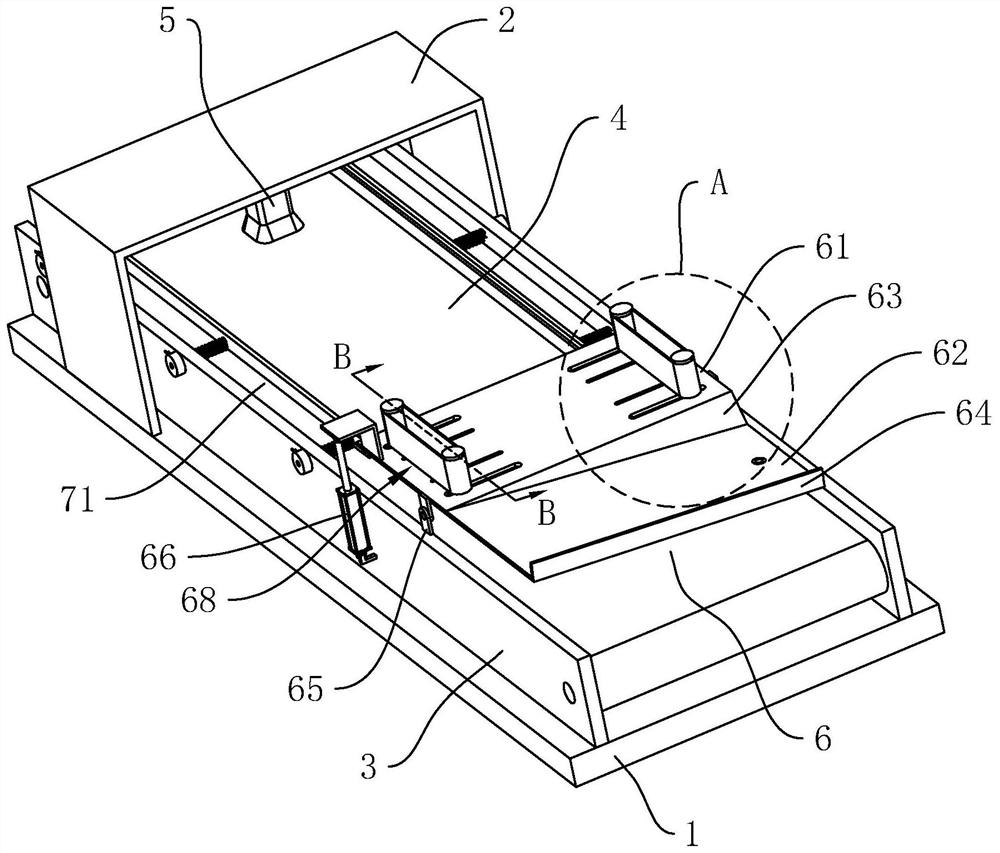
[0036] The embodiment of the present application discloses an SMT patch detection device. refer to figure 1 , The SMT chip detection device includes a base 1 and a cover body 2, and the upper surface of the base 1 is fixed with two support plates 3 parallel to each other, and a conveyor belt 4 for conveying PCBs is provided between the two support plates 3; the cover body 2. It is fixedly installed on the upper surface of the base 1. The cover body 2 is partially covered with two support plates 3. The inner side of the cover body 2 is equipped with an automatic optical detector 5 for detecting SMT patches; the top of the conveyor belt 4 is provided with a rejecting mechanism 6. The rejecting mechanism 6 is used to remove PCBs that do not meet the standard after being detected by the automatic optical detector 5 from the surface of the conveyor belt 4 .

[0037] refer to figure 1 ...


PUM


Abstract

The invention relates to an SMT surface-mount detection device. The device comprises a base and a cover body, two supporting plates are fixedly arranged on the upper surface of the base, and a conveying belt used for conveying a PCB is arranged between the two supporting plates; the inner side of the cover body is provided with an automatic optical detector used for detecting SMT surface-mount; a removing mechanism is arranged above the conveying belt and comprises a bottom plate, the two opposite sides of the bottom plate are hinged to two supporting plates respectively, and the supporting plates are provided with driving parts for driving the bottom plate to swing; a discharging plate is fixed to the side, away from the feeding side of the conveying belt, of the bottom plate; two clamping material conveying belts are arranged above the bottom plate and are used for clamping and conveying PCBs to the discharging plate; the discharging plate is provided with a proximity switch; when the automatic optical detector detects the PCBs which do not meet the standard, the driving parts drives the bottom plate to swing until the edge of one side, away from the discharging plate, of the bottom plate is propped against the upper surface of the conveying belt; and when the proximity switch detects the PCBs, the driving parts drive the bottom plate to swing for resetting. The removing mechanism can remove the PCBs which do not meet the standard from the conveying belt.

Description

technical field [0001] This application relates to the field of printed circuit board production technology, in particular to an SMT chip detection device. Background technique [0002] SMT patch refers to the abbreviation of a series of process processes processed on the basis of PCB, and PCB is a printed circuit board. SMT is surface assembly technology, which is the most popular technology and process in the electronic assembly industry; after SMT patch processing, it is necessary to use automatic optical inspection technology to detect the accuracy of the position of various patch components and the welding of patch components quality situation. PCB boards can range from fine-pitch high-density boards to low-density large-size boards. [0003] The SMT chip detection device usually includes a conveyor belt and an automatic detection device. Usually, the PCB that has passed the SMT chip detection, whether it meets the standard or not, will continue to be transported forw...

Claims


Application Information

Patent Timeline
IPC IPC(8): B07C5/00B07C5/02B07C5/36G01N21/89
CPCB07C5/00B07C5/02B07C5/362G01N21/89
Inventor 周益和杨达利
Owner 深圳市中纬智能有限公司
Why Eureka
Try Eureka