Rare earth metal alloy plate surface layer polishing device

A technology of alloy plate and polishing device, which is applied to surface polishing machine tools, grinding drive devices, metal processing equipment, etc., can solve the problems of uneven polishing of alloy plates, no fixing effect, increased labor, etc., and improve the quality of polishing , The effect of saving the work of pressing the grinding wheel

Active Publication Date: 2021-11-23
东莞市炜安达智能科技有限公司
View PDF9 Cites 4 Cited by
  • Summary
  • Abstract
  • Description
  • Claims
  • Application Information

AI Technical Summary

Problems solved by technology

[0005] In order to overcome the shortcomings of manual operation, increased labor, uneven grinding of the alloy plate and no fixing effect, the technical problem of the present invention is to provide a method that reduces manual operation, has the ability to fix the rare earth alloy plate, and automatically implements reciprocating motion. The surface layer of rare earth alloy plate is evenly polished to make the rare earth alloy plate more beautiful. The rare earth metal alloy plate surface polishing device

Method used


Image

  • Rare earth metal alloy plate surface layer polishing device
  • Rare earth metal alloy plate surface layer polishing device
  • Rare earth metal alloy plate surface layer polishing device

Examples


Embodiment 1

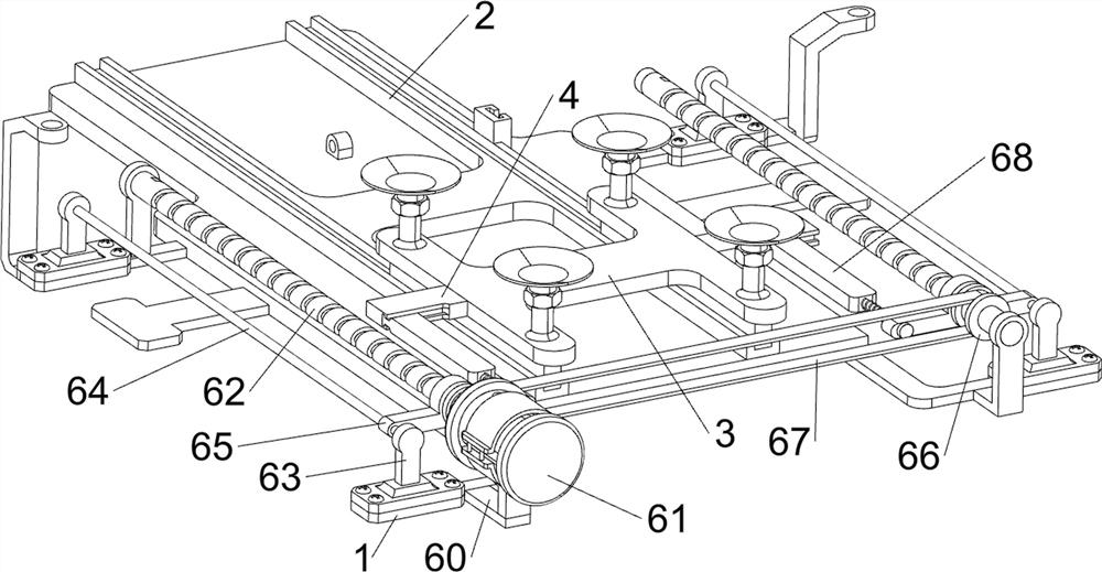
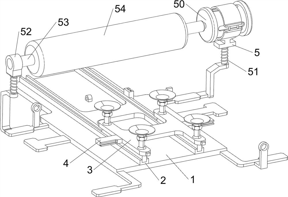
[0096] A rare earth metal alloy plate surface polishing device, such as figure 1 , figure 2 , image 3 , Figure 4 , Figure 5 , Figure 6 , Figure 7 , Figure 8 , Figure 9 and Figure 10 As shown, it includes a bottom plate 1, a guide plate 2, a slide plate 3, a tray 30, a guide block 4, a first motor chassis 5, a servo motor 50, a first return spring 51, a support block 52, a first rotating shaft 53, Grinding wheel 54, propulsion mechanism 6 and clamping mechanism 7, bottom plate 1 top sliding type is connected with guide plate 2, is provided with slide plate 3 slidingly in guide plate 2, and slide plate 3 top front and rear sides are all provided with two pallets 30 , the left and right sides of the sliding plate 3 are provided with guide blocks 4, the top right rear side of the base plate 1 is slidingly provided with a first motor chassis 5, and a first return force spring 51 is connected between the first motor chassis 5 and the top of the base plate 1 , the t...

Embodiment 2

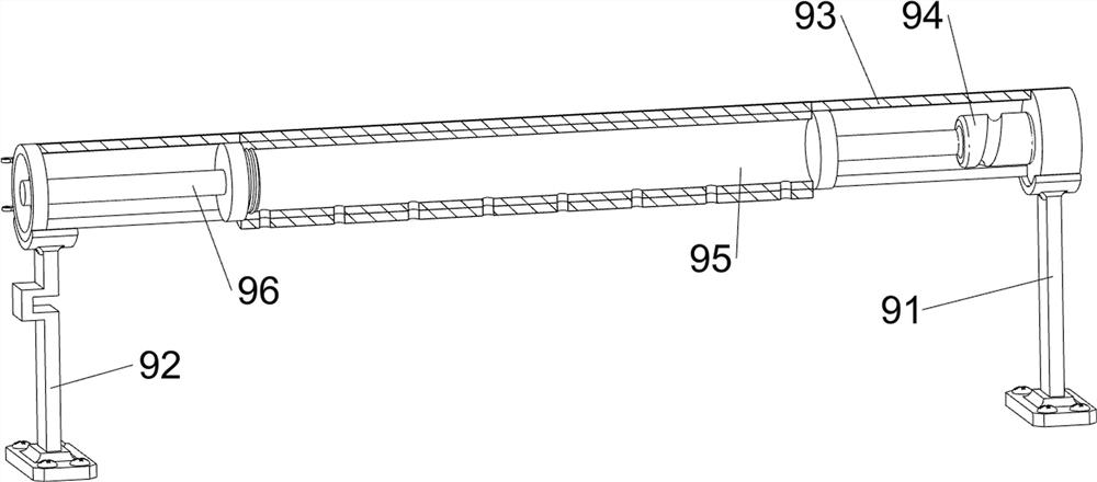
[0103] On the basis of Example 1, such as figure 1 , Figure 9 , Figure 10 , Figure 11 , Figure 12 , Figure 13 , Figure 14 , Figure 15 , Figure 16 , Figure 17 and Figure 18 As shown, a shaking mechanism 8 is also included, and the shaking mechanism 8 includes a gearbox 80, a one-way missing gear 81, a rack frame 82, a block 83, a second limit rod 84 and a fifth return force spring 85, and the top of the bottom plate 1 The right rear side is equipped with a gearbox 80, and the gearbox 80 is in rotation with the right screw mandrel 62. The output shaft of the gearbox 80 is provided with a one-way missing gear 81, and the right side of the guide plate 2 is provided with a block 83, and the block 83 The right side is provided with rack frame 82, and rack frame 82 is meshed with one-way lacking gear 81, and the right side behind guide plate 2 is provided with two second stop rods 84, and the second stop rods 84 are arranged front and back, two A second limiting r...


PUM


Abstract

The invention relates to a polishing device, in particular to a rare earth metal alloy plate surface layer polishing device. According to the rare earth metal alloy plate surface layer polishing device, manual operation is reduced, a rare earth alloy plate can be fixed, reciprocating motion can be automatically carried out, the surface layer of the rare earth alloy plate can be evenly polished, and the rare earth alloy plate is more attractive. The rare earth metal alloy plate surface layer polishing device comprises a bottom plate, a sliding plate and trays; the top of the bottom plate is slidably connected with a guide plate; the sliding plate is arranged in the guide plate in a sliding manner; and the two corresponding trays are arranged on each of the two sides of the top of the sliding plate. A rack frame moves left and right to drive a first poke rod to move left and right, under cooperation of a reciprocating groove roller, a charging pipe continuously rotates, polishing powder continuously falls down to an alloy plate, and the polishing quality can be improved.

Description

technical field [0001] The invention relates to a polishing device, in particular to a polishing device for the surface layer of a rare earth metal alloy plate. Background technique [0002] Rare earth alloy plate is composed of a mixture of rare earth metals or other metals and non-metallic elements, and can be made into binary or multi-element rare earth alloy products. Rare earth alloy plates have unique properties and are widely used in the industrial sector. [0003] At present, in the production and processing of rare earth alloy plates, it is necessary to polish the surface of the rare earth alloy plate to make the rare earth alloy plate more beautiful. The polishing process method uses a polishing disc to manually polish the surface of the rare earth alloy plate. During the grinding work, it is necessary to manually place the polishing disc on the surface of the rare earth alloy plate for reciprocating motion, so that the contact area between the polishing disc and t...

Claims


Application Information

Patent Timeline
Patent Type & Authority Applications(China)
IPC IPC(8): B24B29/02B24B41/02B24B41/04B24B41/06B24B47/12B24B47/20B24B47/22
CPCB24B29/02B24B41/02B24B41/04B24B41/06B24B47/12B24B47/22B24B47/20
Inventor 黄美林
Owner 东莞市炜安达智能科技有限公司
Why Eureka
Try Eureka