Stamping system for plate heat exchanger sealing gasket production and machining and stamping method thereof

A technology for plate heat exchangers and gaskets, applied in applications, household components, household appliances, etc., can solve problems such as large thickness errors, difficulty in taking out, and deformation of gaskets, and achieve simple and convenient operation, changing the pouring area, and complete pouring effect

Active Publication Date: 2021-11-23
安徽凌谊密封科技有限公司
View PDF7 Cites 2 Cited by
  • Summary
  • Abstract
  • Description
  • Claims
  • Application Information

AI Technical Summary

Problems solved by technology

However, this stamping method is likely to cause serious deformation of the gasket
[0007]Some gaskets are produced by pouring, specifically pouring into the grooved mold, and taking the gasket out of the groove after it is formed

Method used


Image

  • Stamping system for plate heat exchanger sealing gasket production and machining and stamping method thereof
  • Stamping system for plate heat exchanger sealing gasket production and machining and stamping method thereof
  • Stamping system for plate heat exchanger sealing gasket production and machining and stamping method thereof

Examples


Embodiment 1

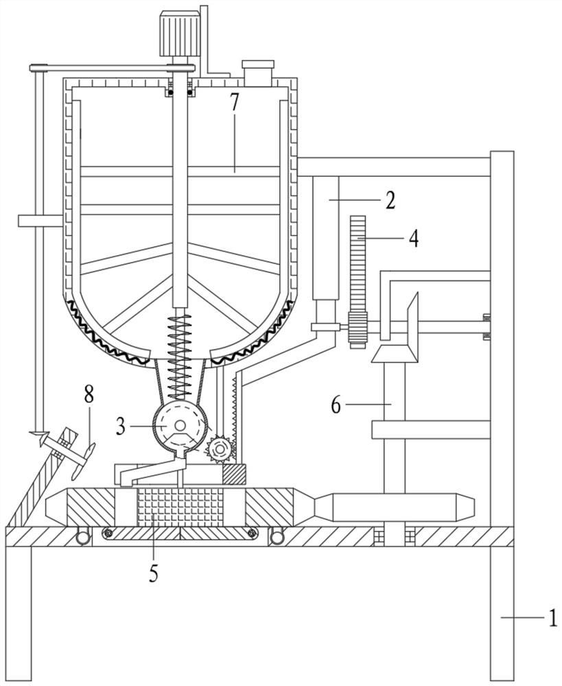
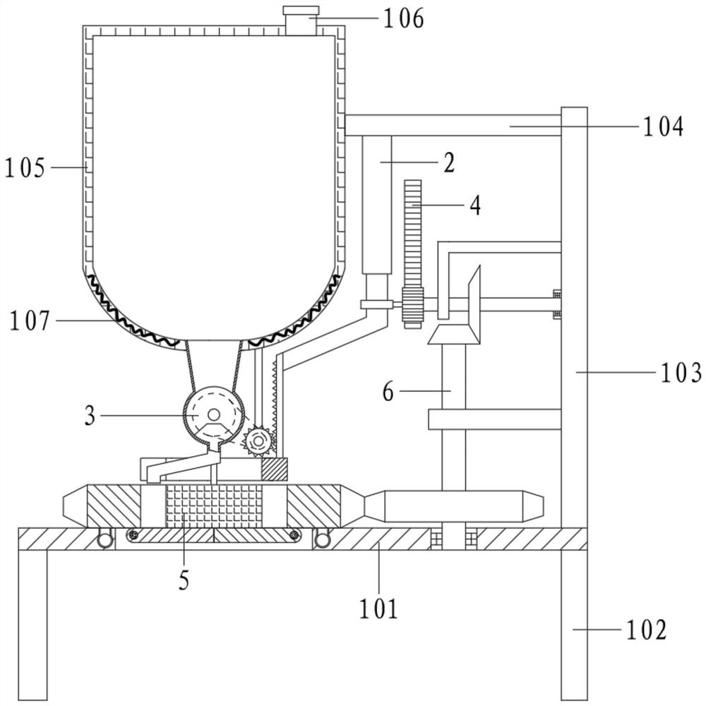
[0062] Referring to the accompanying drawings, a stamping system for the production and processing of plate heat exchanger gaskets includes a frame component 1, a stamping component 2, a casting component 3, a transmission component 4, a mold component 5 and a rotating component 6;

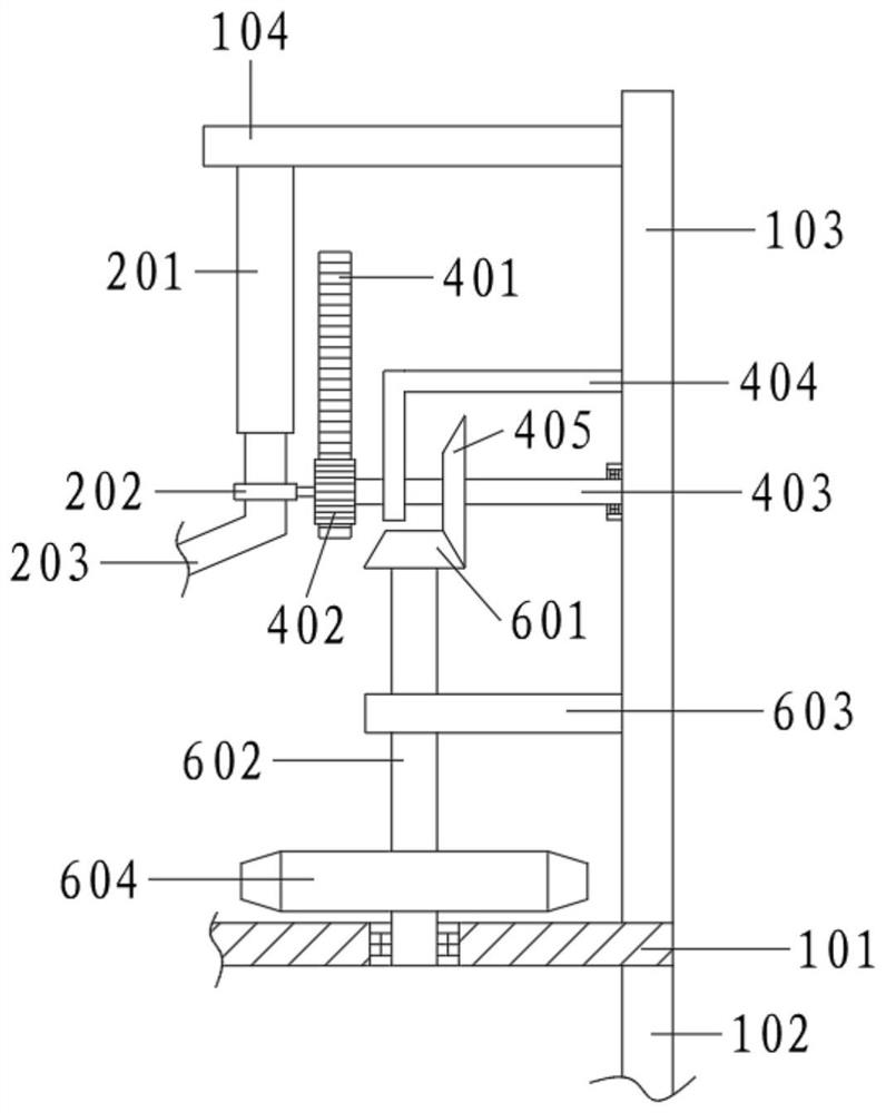
[0063] Frame assembly 1 comprises support 101, support leg 102, side plate 103, ejector rod 104 and raw material bucket 105, and support leg 102 is connected under support 101, and the right end of support 101 is upwardly connected with side plate 103; The top of the seat 101 is connected to the side plate 103 through the push rod 104; the top of the raw material barrel 105 is provided with a feeding port 106, and the bottom is provided with a heater 107;

[0064] The pouring assembly 3 is connected below the raw material barrel 105, and the mold assembly 5 is correspondingly arranged on the support 101; the stamping assembly 2 is connected below the top plate, and the stamping assembly 2 extends a...

Embodiment 2

[0066] Referring to the accompanying drawings, a stamping system for the production and processing of plate heat exchanger gaskets includes a frame component 1, a stamping component 2, a casting component 3, a transmission component 4, a mold component 5 and a rotating component 6;

[0067] Frame assembly 1 comprises support 101, support leg 102, side plate 103, ejector rod 104 and raw material bucket 105, and support leg 102 is connected under support 101, and the right end of support 101 is upwardly connected with side plate 103; The top of the seat 101 is connected to the side plate 103 through the push rod 104; the top of the raw material barrel 105 is provided with a feeding port 106, and the bottom is provided with a heater 107;

[0068] The pouring assembly 3 is connected below the raw material barrel 105, and the mold assembly 5 is correspondingly arranged on the support 101; the stamping assembly 2 is connected below the top plate, and the stamping assembly 2 extends a...

Embodiment 3

[0088] On the basis of the above examples,

[0089] It also includes a stirring component; the stirring component includes a mounting frame 701, a driving motor 702, a stirring shaft 703, a stirring rod 704 and a scraper 705;

[0090]The driving motor 702 is connected to the outer top of the raw material barrel 105 through the mounting frame 701, and the driving motor 702 is connected with the stirring shaft 703 downward, and the stirring shaft 703 stretches into the raw material barrel 105 and is connected with some stirring rods 704; the outer end of the stirring rod 704 is also connected with a The scraper 705 is attached to the inner wall of the raw material barrel 105 .

[0091] Specifically, the heater 107 heats and melts the raw material, and at the same time starts the driving motor 702 to drive the stirring shaft 703 to rotate, so that the stirring rod 704 rotates with the scraper 705, the stirring rod 704 keeps the raw material fluidity, and the scraper 705 reduces t...


PUM


Abstract

The invention relates to the technical field of sealing gasket stamping equipment, in particular to a stamping system for plate heat exchanger sealing gasket production and machining and a stamping method thereof. During pouring, an electric control telescopic rod is controlled to contract, namely, a connecting block moves upwards, on one hand, the connecting block is matched with a pouring assembly through a stamping assembly, a groove faces a pouring pipe, molten raw materials in the groove are injected into a pouring cavity from the pouring pipe, and at the moment, a torsional spring enables a blocking door to block the bottom of a pouring grooves, on the other hand, the connecting block drives the rotating assembly through a transmission assembly to enable an outer gear ring to rotate, so that the pouring area is changed, and complete pouring is achieved, during stamping, the electric control telescopic rod is controlled to extend, on the contrary, a first rack and a stamping ring move downwards, the stamping ring stretches into a pouring cavity and extrudes a sealing gasket, a blocking door is extruded by the upper portion to be automatically opened, and therefore the sealing gasket automatically falls off, and a rotating disc reversely deflects to enable the groove to face the material guide pipe again for next casting molding and stamping.

Description

technical field [0001] The invention relates to the technical field of stamping equipment for gaskets, and relates to a stamping system and a stamping method for producing and processing gaskets of plate heat exchangers. Background technique [0002] The plate heat exchanger is a high-efficiency heat exchanger composed of a series of metal sheets with a certain corrugated shape. Thin rectangular passages are formed between various plates of the plate heat exchanger, and heat is exchanged through the plates. [0003] Plate heat exchanger is an ideal equipment for liquid-liquid, liquid-vapor heat exchange. It has the characteristics of high heat exchange efficiency, small heat loss, compact and light structure, small footprint, wide application and long service life. [0004] Under the same pressure loss, after testing, the heat transfer coefficient of the plate heat exchanger is 3-5 times higher than that of the tube heat exchanger, and the floor area is one-third of the tu...

Claims


Application Information

Patent Timeline
IPC IPC(8): B29C39/02B29C39/22B29C39/26B29C39/36B29L31/26
CPCB29C39/02B29C39/22B29C39/26B29C39/36B29L2031/265Y02P70/10
Inventor 胡西芹王文军解园园
Owner 安徽凌谊密封科技有限公司
Why Eureka
Try Eureka