A Disposable Tableware Forming Machine Convenient for Retrieving Materials

A one-time, easy-to-take technology, applied to household appliances, other household appliances, household components, etc., can solve problems such as stacking too high, inconvenient retrieval of tableware, and affecting normal stacking work, so as to avoid stacking too high, It is convenient and quick to adjust to ensure the effect of normal stacking

Active Publication Date: 2022-02-22
江苏维昌生物科技有限公司
View PDF0 Cites 0 Cited by
  • Summary
  • Abstract
  • Description
  • Claims
  • Application Information

AI Technical Summary

Problems solved by technology

[0003] In the existing disposable tableware forming equipment, the tableware falls in the stacked place after being processed and formed. When the staff takes it, it will affect the normal progress of subsequent tableware falling and stacking. If the staff does not take away the stacked tableware in time, It is easy to stack too high, which will affect the normal progress of subsequent stacking work. At the same time, the place where the tableware falls is not convenient for picking up materials, and there are certain limitations in use.

Method used


Image

  • A Disposable Tableware Forming Machine Convenient for Retrieving Materials
  • A Disposable Tableware Forming Machine Convenient for Retrieving Materials
  • A Disposable Tableware Forming Machine Convenient for Retrieving Materials

Examples


Embodiment 1

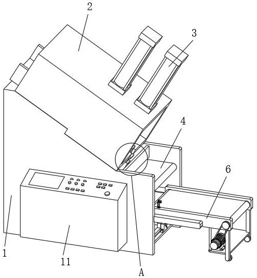
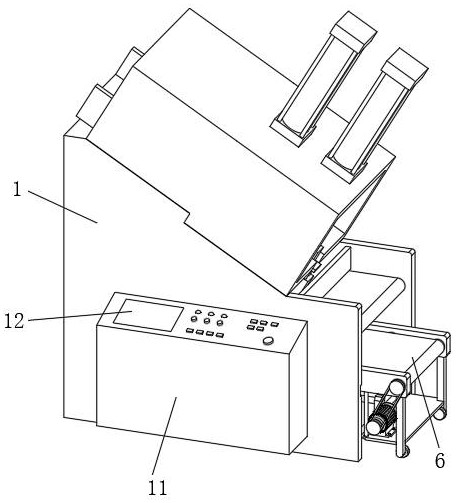
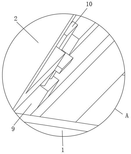
[0034] Such as Figure 1-Figure 8 As shown, a disposable tableware forming machine for convenient material removal comprises a support 1, a forming box 2 is fixedly installed on the support 1, and a forming cylinder 3 is installed on the forming box 2, and a jacking cylinder is arranged in the support 1, and The jacking cylinder and the forming cylinder 3 are respectively provided with forming molds, the support 1 is provided with a transmission belt 4, and the control box 11 is fixedly installed on the support 1, and the telescopic cylinder 9 is installed on the support 1, and the telescopic cylinder 9 is provided with The baffle 10, the support 1 is provided with a chute 5, and the support 1 is provided with a conveying mechanism 6, and the conveying mechanism 6 includes a support frame 601, a slider 602, a driving roller 603, a driven roller 604, a conveyor belt 605, a support plate 606, conveying motor 607, transmission wheel 608, supporting leg 609 and roller 610, the inn...

Embodiment 2

[0037] Such as Figure 1-Figure 8 As shown, the components that are the same as or corresponding to those in the first embodiment are marked with the corresponding reference numerals in the first embodiment. For the sake of simplicity, only the differences from the first embodiment will be described below. The difference between this embodiment two and embodiment one is: as Figure 5 As shown, the slider 602 is fixed on the support frame 601, and the slider 602 is connected in the chute 5, the support frame 601 is slidingly connected between the slider 602, the chute 5 and the bracket 1, and the conveyor belt 605 is arranged on the support frame Inner side of 601, support leg 609 is fixed on the lower surface of one end of support frame 601, support plate 606 is fixed between support frame 601 and support leg 609, conveying motor 607 is installed on support plate 606, driving roller 603 is arranged on support frame 601 One end of the inner side, the driven roller 604 is set o...

Embodiment 3

[0040] Such as Figure 1-Figure 8 As shown, the components that are the same as or corresponding to those in the first embodiment are marked with the corresponding reference numerals in the first embodiment. For the sake of simplicity, only the differences from the first embodiment will be described below. The difference between the third embodiment and the first embodiment is: as Image 6 As shown, the nut base 702 is arranged on the suspension 701, the servo motor 706 is connected with the screw rod 707, and the screw rod 707 passes through the nut base 702, the rotating base 704 is fixed on the fixed plate 703, and the fixed plate 703 is fixed on the The inner side of the support 1, the suspension 701 is fixed on the conveying mechanism 6, the nut seat 702 is fixedly installed on the suspension 701, and the nut seat 702 is provided with an adjustment hole, the fixed plate 703 is fixedly installed on the inner side of the support 1, and the fixed plate 703 is provided with ...


PUM


Abstract

The invention discloses a disposable tableware molding machine which is convenient for taking materials, which comprises a bracket, a molding box is fixedly installed on the bracket, and a molding cylinder is installed on the molding box, a jacking cylinder is arranged inside the bracket, and The lifting cylinder and the forming cylinder are respectively provided with a forming mold, the support is provided with a transmission belt, and a control box is fixedly installed on the support, a telescopic cylinder is installed on the support, and a baffle is provided on the telescopic cylinder. The invention relates to a disposable tableware molding machine that is convenient for taking materials, and belongs to the field of tableware production equipment. Connection, the adjustment of the position of the conveying mechanism is carried out in a mechanical way, which is convenient and quick to adjust. The infrared sensor is used to detect the stacking height of the tableware, which can provide timely feedback information, which is convenient for the conveying mechanism to move and give way.

Description

technical field [0001] The invention relates to the field of tableware production equipment, in particular to a disposable tableware forming machine which is convenient for taking out materials. Background technique [0002] Along with improving constantly of people's living standard, various disposable paper daily necessities emerge in an endless stream, wherein the use of disposable tableware is particularly extensive. Disposable tableware refers to tableware that is used only once, including disposable tableware, cups, and spoons. Disposable tableware is usually divided into two categories: plastic products and paper products. Plastic disposable tableware is generally formed by thermoplastic processing, while paper disposable tableware is processed by stamping. During the production and processing of paper disposable tableware, the cut materials are placed on the forming equipment, and the stamping structure in the forming equipment is used for forming. The formed tablew...

Claims


Application Information

Patent Timeline
Patent Type & Authority Patents(China)
IPC IPC(8): B29C51/00B29C51/26B29C51/46B29L31/28
Inventor 刘倻
Owner 江苏维昌生物科技有限公司
Why Eureka
Try Eureka