A Tire Angle Estimation Method Based on Vehicle Trajectory

A vehicle track and corner technology, applied to vehicle components, steering mechanisms, steering rods, etc., can solve the problems of complex installation, inability to obtain tire angles, high price, etc., and achieve high stability

Active Publication Date: 2022-05-17
SHANGHAI ALLYNAV TECH CO LTD
View PDF0 Cites 0 Cited by
  • Summary
  • Abstract
  • Description
  • Claims
  • Application Information

AI Technical Summary

Problems solved by technology

In the automatic driving steering control of agricultural machinery, it is necessary to use the tire rotation angle as a feedback quantity to control the vehicle in real time; accurate measurement of the tire rotation angle is one of the important prerequisites for realizing the steering control of agricultural machinery; the traditional method of measuring the tire rotation angle is to install on the tire Hall angle sensor, the reading of the sensor is used as the measurement value of the tire angle. Although it is accurate, this method has disadvantages such as complicated installation, high price, and easy wear; Install a gyroscope on each of them, calculate the relative coordinates between the two and estimate it by fusing it with the speed information of the vehicle, but this method is also expensive; under ideal conditions, the tire rotation angle can be obtained through the steering wheel rotation angle and the vehicle transmission. ratio; if an encoder is installed on the steering wheel to read the steering wheel angle, the tire angle can be directly calculated through the transmission ratio; There is an inconsistency in the relationship between the tire rotation angle: when the steering wheel rotation angle changes, the tire rotation angle does not change; agricultural machinery and vehicles have problems of aging and wear during use, so the problems of pressure relief and clearance are inevitable; when these two problems exist When using the steering wheel angle and gear ratio, the exact tire angle cannot be obtained

Method used


Image

  • A Tire Angle Estimation Method Based on Vehicle Trajectory
  • A Tire Angle Estimation Method Based on Vehicle Trajectory
  • A Tire Angle Estimation Method Based on Vehicle Trajectory

Examples


Embodiment Construction

[0043] The following will clearly and completely describe the technical solutions in the embodiments of the present invention with reference to the accompanying drawings in the embodiments of the present invention. Obviously, the described embodiments are only some, not all, embodiments of the present invention. Based on the embodiments of the present invention, all other embodiments obtained by persons of ordinary skill in the art without making creative efforts belong to the protection scope of the present invention.

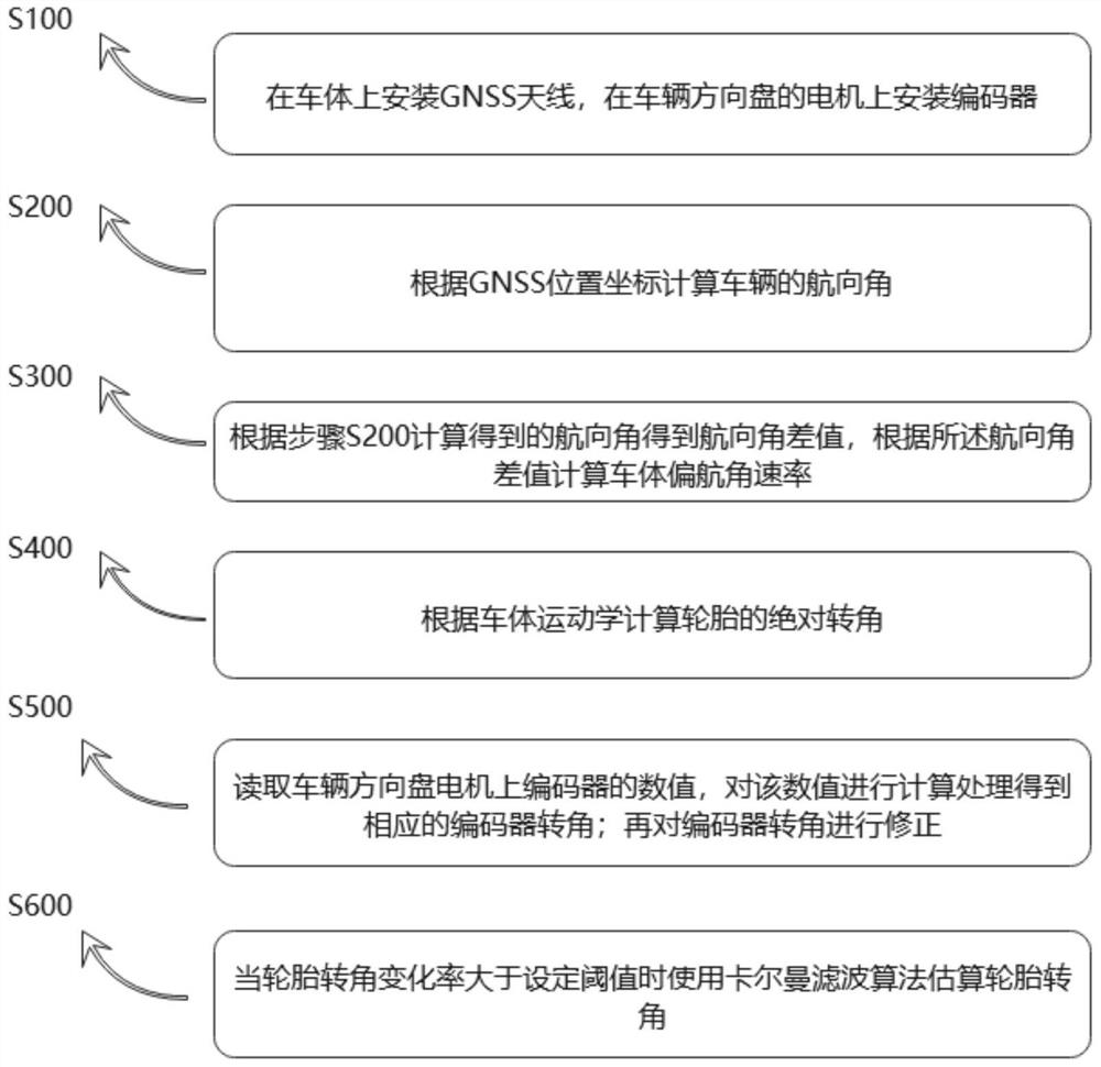
[0044] see figure 1 , the present invention provides a technical solution: a tire rotation angle estimation method based on vehicle trajectory, the estimation method includes:

[0045] S100: Install the GNSS antenna on the car body, and install the encoder on the motor of the steering wheel of the vehicle;

[0046] S200: Calculate the heading angle of the vehicle according to the GNSS position coordinates; wherein, step S200 includes:

[0047] S201: Obtain t...


PUM


Abstract

The invention discloses a tire rotation angle estimation method based on vehicle trajectory: S100: install a GNSS antenna on the vehicle body, and install an encoder on the motor of the steering wheel of the vehicle; S200: calculate the heading angle of the vehicle according to the GNSS position coordinates; S300: according to Calculate the heading angle to get the heading angle difference and the yaw rate of the car body; S400: calculate the absolute rotation angle of the tire according to the kinematics of the car body; S500: read the value of the encoder on the steering wheel motor of the vehicle, and calculate and process the value Obtain the corresponding encoder angle; then correct the encoder angle; S600: use the Kalman filter algorithm to estimate the tire angle when the rate of change of the tire angle is greater than the set threshold; the invention combines the long-term stability of the tire angle based on the vehicle trajectory calculation and through The short-term accuracy of the tire rotation angle calculated by the encoder is high, and it can provide accurate and stable tire rotation angle under the normal operation of agricultural machinery and vehicles.

Description

technical field [0001] The invention relates to the technical field of automatic control, in particular to a tire rotation angle estimation method based on vehicle trajectory. Background technique [0002] The automatic driving system of agricultural machinery is an equipment system that controls the steering of the vehicle according to the position information of the vehicle. In the automatic driving steering control of agricultural machinery, it is necessary to use the tire rotation angle as a feedback quantity to control the vehicle in real time; accurate measurement of the tire rotation angle is one of the important prerequisites for realizing the steering control of agricultural machinery; the traditional method of measuring the tire rotation angle is to install on the tire Hall angle sensor, the reading of the sensor is used as the measurement value of the tire rotation angle. Although it is accurate, this method has disadvantages such as complicated installation, high...

Claims


Application Information

Patent Timeline
Patent Type & Authority Patents(China)
IPC IPC(8): B62D15/02B62D6/00B62D113/00B62D137/00
CPCB62D15/024B62D6/001B62D6/002
Inventor 具大源李晓宇张兴兴
Owner SHANGHAI ALLYNAV TECH CO LTD
Why Eureka
Try Eureka