
Knee joint thighbone posterior condyle point identification method and system based on motion simulation algorithm

A technology of motion simulation and recognition method, which is applied in the field of computer vision, can solve the problems of high error, great subjectivity, and the inability to realize the precise positioning of the posterior femoral condyle point of the knee joint, etc., to achieve fast and accurate positioning, efficient and accurate recognition results, and detection effects stable effect

Active Publication Date: 2021-11-23
LONGWOOD VALLEY MEDICAL TECH CO LTD +1
View PDF20 Cites 4 Cited by
  • Summary
  • Abstract
  • Description
  • Claims
  • Application Information

AI Technical Summary

Problems solved by technology

The inventors found that the deep learning point recognition algorithm needs to accurately mark the posterior condyle points when identifying the posterior condyle points of the knee joint, but in the process of marking the posterior condyle points on the three-dimensional model Subjectivity leads to high error, and the precise positioning of the posterior femoral condyle point of the knee joint cannot be achieved

Method used


Image

  • Knee joint thighbone posterior condyle point identification method and system based on motion simulation algorithm
  • Knee joint thighbone posterior condyle point identification method and system based on motion simulation algorithm
  • Knee joint thighbone posterior condyle point identification method and system based on motion simulation algorithm

Examples


Embodiment Construction

[0023] The specific embodiments of the present invention will be described in detail below in conjunction with the accompanying drawings, but it should be understood that the protection scope of the present invention is not limited by the specific embodiments.

[0024] Unless expressly stated otherwise, throughout the specification and claims, the term "comprise" or variations thereof such as "includes" or "includes" and the like will be understood to include the stated elements or constituents, and not Other elements or other components are not excluded.

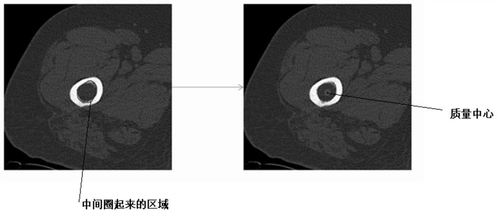
[0025] In order to overcome the problem of low recognition accuracy of the posterior condyle point in the prior art, a method for recognizing the posterior condyle point of the knee joint femur based on a motion simulation algorithm is provided in one embodiment, such as figure 1 As shown, the method includes: step S1 to step S7.

[0026] In step S1, the coordinates of the center point of the medullary cavity at each slice...


PUM


Abstract

The invention discloses a knee joint thighbone posterior condyle point identification method and system based on a motion simulation algorithm. The method comprises the steps of determining coordinates of a medullary cavity center point of each fault layer in a two-dimensional CT image of a knee joint thighbone based on an image identification technology; fitting a medullary cavity axis according to the coordinates of the medullary cavity center points of all the fault layers; performing three-dimensional reconstruction on the two-dimensional CT image to obtain a three-dimensional model of the femur; performing three-dimensional graphic transformation on the axis of the medullary cavity in the three-dimensional model to enable the axis of the medullary cavity to be perpendicular to the horizontal plane; obtaining a perspective image of one end of the femur according to the three-dimensional model; based on the perspective image, rotating the femur by taking the axis of the medullary cavity as the center, so that the longitudinal coordinates of the posterior condyle points on the two sides of the femur are the same; and restoring the bilateral posterior condyle points of the thighbone in the perspective image to the three-dimensional model to obtain three-dimensional coordinates of the bilateral posterior condyle points of the thighbone of the knee joint. The knee joint thighbone posterior condyle point can be accurately positioned.

Description

technical field [0001] The invention relates to the technical field of computer vision, in particular to a method and system for identifying a knee femoral posterior condyle point based on a motion simulation algorithm. Background technique [0002] The posterior condyle point of the knee joint is an important anatomical position of the knee femur, and it is an important reference point in knee joint surgery. The posterior condyle point is usually defined as the contact point between the posterior condyle and the horizontal plane when the axis of the femoral medullary cavity is parallel to the horizontal plane. . At present, related technologies can usually use point recognition algorithms in deep learning to identify posterior condyle points. The inventors found that the deep learning point recognition algorithm needs to accurately mark the posterior condyle points when identifying the posterior condyle points of the knee joint, but in the process of marking the posterior ...

Claims


Application Information

Patent Timeline
IPC IPC(8): G06T7/00G06T7/62G06T3/00G06T17/00
CPCG06T7/0012G06T7/62G06T17/00G06T2207/10081G06T2207/30008G06T3/08
Inventor 张逸凌刘星宇
Owner LONGWOOD VALLEY MEDICAL TECH CO LTD
Learn More