Drive assembly

A technology for driving components and windings, which is applied in the direction of electric components, windings, and control/drive circuits, etc., and can solve the problems of large overall height changes and large tolerances of laminated stator cores.

Pending Publication Date: 2021-11-23
FTE汽车有限责任公司
View PDF0 Cites 0 Cited by
  • Summary
  • Abstract
  • Description
  • Claims
  • Application Information

AI Technical Summary

Problems solved by technology

[0004] The problem with this mode of construction is that the laminated stator core as a whole has very large tolerances, so the overall height of

Method used


Image

  • Drive assembly
  • Drive assembly
  • Drive assembly

Examples


Embodiment Construction

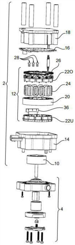
[0030] In perspective view, figure 1 A drive assembly with an electric motor 2 and an oil pump 4 is shown. The oil pump serves to provide a flow of hydraulic oil, whereby in particular the transmission actuators of the motor vehicle can be supplied. The electric motor 2 is used to drive the pump 4 .

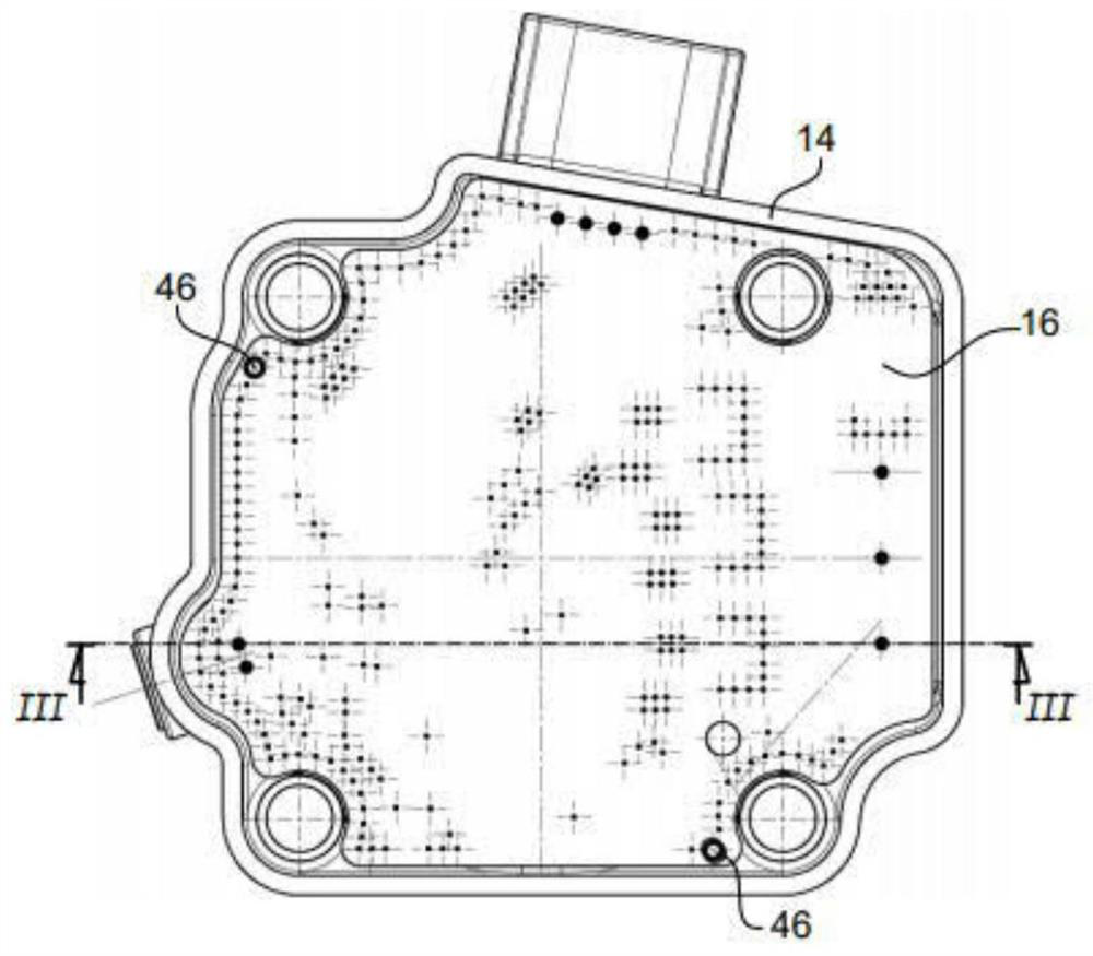
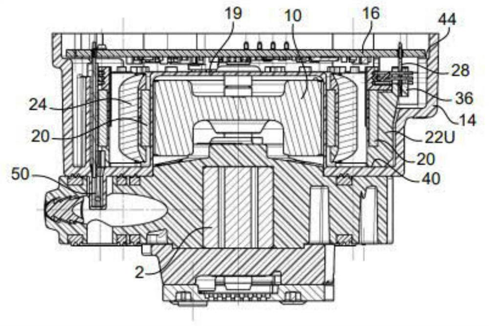
[0031] The electric motor 2 has a rotor 10 which is spatially arranged in a stator 12 . The stator 12 is arranged in a stator housing 14 which also houses a printed circuit board 16 . A housing cover 18 is also provided.

[0032] The stator housing 14 has a dome-shaped structure 19 such that although the rotor 10 is arranged inside the stator 12 it is still outside the stator housing 14 .

[0033] The stator housing 14 is preferably an injection molded part made of plastic.

[0034] The stator 12 has a core 20 consisting of stator laminations, which is assigned a stator insulation 22 formed from a lower part 22U and an upper part 22O. Furthermore, a winding 24 is provided f...


PUM


Abstract

The invention relates to a drive assembly having an electric motor (2), having a stator housing (14), a stator (12) accommodated therein and having at least one winding (24), a stator insulation (22) which has a lower part (22U) and an upper part (22O), wherein the lower part (22U) rests against at least one bearing surface (40) in the stator housing (14), terminal contacts (28) for the winding (24), wherein the terminal contacts (28) are held in a contact carrier (36), which is provided on the lower part (22U) of the stator insulation (22), and a printed circuit board (16), which rests on at least one supporting surface (42) in the stator housing (14), wherein the terminal contacts (28) are in contact with associated conductor tracks of the printed circuit board (16).

Description

technical field [0001] The invention relates to a drive assembly with an electric motor, which is particularly useful for providing a flow of hydraulic oil that can be used for a transmission actuator or for cooling and / or lubricating a transmission of a motor vehicle. Background technique [0002] The electric motor of the drive assembly can have a stator housing in which the stator of the electric motor and a printed circuit board are arranged for contacting the stator winding. The stator windings themselves are wound on the stator insulation within which the stator laminations are located. [0003] The stator insulation may be an injection molded part which is welded to the stator lamination pack. In the present case, however, the stator insulation consists of an upper part and a lower part assembled in such a way that the laminated stator core is accommodated between them. [0004] The problem with this mode of construction is that the laminated stator core as a whole ...

Claims


Application Information

Patent Timeline
IPC IPC(8): H02K11/33H02K3/38H02K3/50H02K5/22F04B17/04
CPCH02K11/33H02K3/38H02K3/50H02K5/225F04B17/04H02K5/04H02K2203/03H02K2203/06H02K2203/12H02K3/325H02K3/522H02K2211/03
Inventor R.斯托塞尔
Owner FTE汽车有限责任公司
Why Eureka
Try Eureka