
Energy efficiency optimization method for auxiliary backscatter communication system of multi-rotor unmanned aerial vehicle

A multi-rotor unmanned aerial vehicle, backscattering technology, applied in scattering propagation systems, radio transmission systems, transmission systems, etc., can solve the problems of limited communication distance, large number of receivers, and increased construction costs of the Internet of Things, and achieve savings Cost, excellent communication quality, and the effect of saving airframe energy

Active Publication Date: 2021-11-23
YANSHAN UNIV
View PDF6 Cites 0 Cited by
  • Summary
  • Abstract
  • Description
  • Claims
  • Application Information

AI Technical Summary

Problems solved by technology

The communication distance of the backscatter communication system is limited, and the distance between the receiver and the backscatter device must be kept within its communication range (on the order of hundreds of meters). Therefore, in large-scale IoT application scenarios, in order to cover all backscatter The number of equipment and receivers is likely to become extremely large, and the deployment of a large number of receivers will significantly increase the construction cost of the Internet of Things

Method used


Image

  • Energy efficiency optimization method for auxiliary backscatter communication system of multi-rotor unmanned aerial vehicle
  • Energy efficiency optimization method for auxiliary backscatter communication system of multi-rotor unmanned aerial vehicle
  • Energy efficiency optimization method for auxiliary backscatter communication system of multi-rotor unmanned aerial vehicle

Examples


Embodiment Construction

[0051] Below in conjunction with embodiment the present invention is described in further detail:

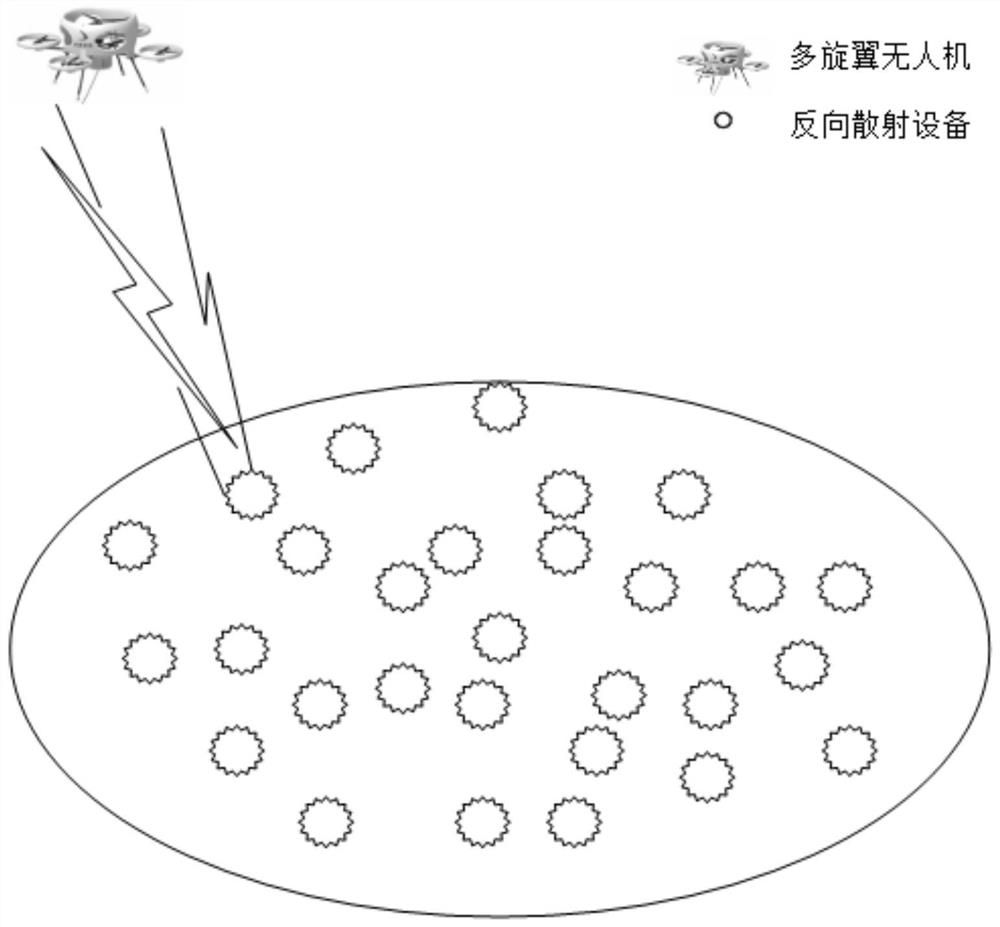
[0052] figure 1 It is a model diagram of the multi-rotor drone-assisted backscatter communication system of the present invention. In the system structure, there is a multi-rotor drone and K backscatter devices, and the K backscatter devices have been deployed in a predetermined area. The multi-rotor UAV acts as a mobile signal transmitter and signal receiver. The backscatter device can collect the signal emitted by the multi-rotor UAV to provide energy for its own operation, and change the antenna load impedance to make the amplitude of the signal reflected by the antenna , frequency or phase changes and then transmit information to the signal receiver of the multi-rotor UAV, and the multi-rotor UAV starts from the starting point to collect information and then returns to the starting point.

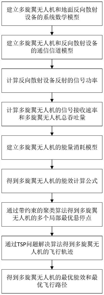
[0053] figure 2 It is a flow chart of the multi-rotor drone-assisted backscatter c...


PUM


Abstract

The invention discloses an energy efficiency optimization method for an auxiliary backscatter communication system of a multi-rotor unmanned aerial vehicle. The method comprises the following steps: enabling a multi-rotor unmanned aerial vehicle to serve as a mobile signal transmitter and a signal receiver, and enabling backscatter equipment to collect a signal transmitted by the multi-rotor unmanned aerial vehicle, and providing energy for the operation of the multi-rotor unmanned aerial vehicle; obtaining a system mathematical model and a communication channel model of the multi-rotor unmanned aerial vehicle and the backscatter equipment according to the position relation and the communication channel condition of the multi-rotor unmanned aerial vehicle and the backscatter equipment; calculating the distance and the energy loss rate between the multi-rotor unmanned aerial vehicle and the backscatter equipment according to the system mathematical model and the communication channel model, and obtaining a motion model and an energy consumption model of the multi-rotor unmanned aerial vehicle; and finally, under the constraint conditions of the signal-to-noise ratio and the throughput, adopting a clustering algorithm with constraints and a TSP problem solving algorithm to obtain the optimal flight path and the optimal energy efficiency of the multi-rotor unmanned aerial vehicle.

Description

technical field [0001] The invention relates to the technical field of wireless communication, in particular to an energy efficiency optimization method for a multi-rotor UAV-assisted backscatter communication system. Background technique [0002] The Internet of Things is the link connecting the physical world and the digital world, and a key enabling technology for ubiquitous perception and computing. The large-scale deployment of the Internet of Things is limited by sensor energy consumption, deployment and maintenance costs. Therefore, how to break through the shackles of the above constraints has become a common concern of academia and industry. Backscatter communication technology has become a breakthrough to break the limitation and promote the emergence of the passive Internet of Things because it enables the sensor to capture energy from the surrounding signal transmitter or the wireless signal of the environment for computing and communication without the need for...

Claims


Application Information

Patent Timeline
Patent Type & Authority Applications(China)
IPC IPC(8): H04B7/185H04B7/22
CPCH04B7/18506H04B7/22Y02D30/70
Inventor 郭希娟李岩常征
Owner YANSHAN UNIV
Learn More