

Dephosphorization device for copper rod rolling mill
A technology for rolling mills and copper rods, applied in the field of dephosphorization devices for copper rod rolling mills, can solve the problems of poor effect and insufficient cleaning of the surface of copper rods, etc., and achieve the effect of improving cleaning efficiency and cleaning effect
- Summary
- Abstract
- Description
- Claims
- Application Information
AI Technical Summary
Problems solved by technology
Method used
Image

Examples
Embodiment 1
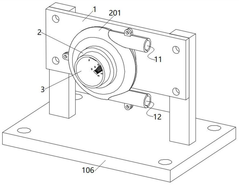
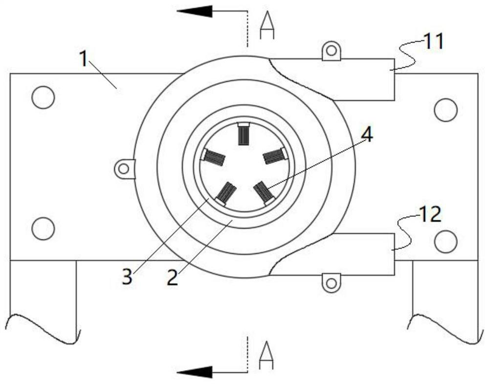
[0035] Such as figure 1 and 2 As shown, the present invention is a phosphorus removal device for a copper rod rolling mill, including a fixed plate 1 , an end sleeve 2 and a cleaning pipe sleeve 3 . The side of the fixed plate 1 is connected with two support rods by screws, and the lower end of the support rods is welded with a fixed base 106 for connecting and fixing with the rolling mill through the fixed base 106 .
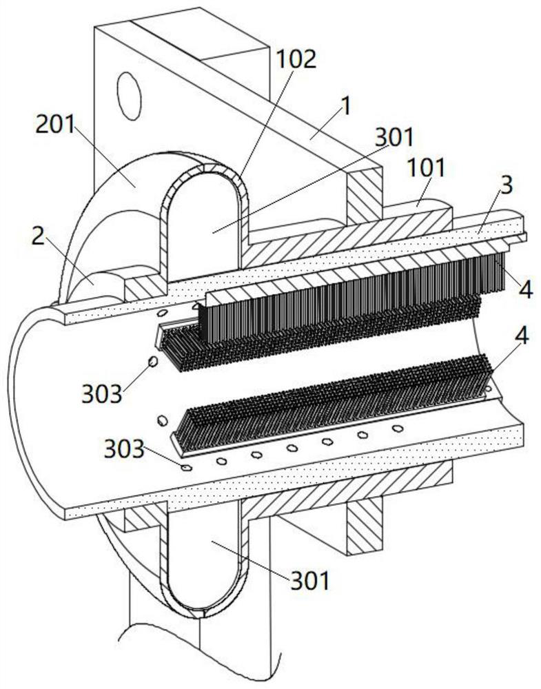
[0036] Such as image 3 and 4 As shown, the fixing plate 1 is provided with a round hole, and a fixing sleeve 101 is welded or flanged in the round hole. One end of the fixing sleeve 101 is provided with a first arc-shaped flange 102 facing outward; the outer wall of the first arc-shaped flange 102 is welded or integrally formed with a first upper groove plate 103 and a first lower groove plate 104 .
[0037] One end of the end sleeve 2 is provided with an outwardly facing second arc-shaped flange 201 ; the outer wall of the second arc-shaped flange 201 is ...
Embodiment 2
[0047] In order to improve the cleaning effect, such as Figure 7 and 8 As shown, the spraying through opening is set as a rectangular slit structure 304, so that the coverage of the emulsion ejected by the rectangular slit structure 304 increases, and during the rotation of the cleaning sleeve 3, it sweeps across the surface of the copper rod, This helps to improve the overall cleaning effect.
Embodiment 3
[0049] On the basis of embodiment one or embodiment two, such as image 3 , 5 Shown in and 6, several brush strips 4 are fixedly connected to the inner wall of the cleaning pipe sleeve 3 . At the same time, the brush bar 4 and the rectangular sinker 302 are arranged at intervals, so that when the emulsion is sprayed toward the copper pipe, the cleaning sleeve 3 drives the brush bar 4 to rotate, so that the surface of the copper rod is cleaned by the brush bar 4, so that the bonding The copper powder, etc. have been thoroughly cleaned.
[0050] Wherein, cleaning sleeve 3 inner wall is provided with two to four dovetail grooves 305; The screws secure the insert 401 in the dovetail slot 305 .
[0051] When installing, insert the cutting strip 401 from the end of the dovetail groove 305, so that the brush strip 4 is located inside the cleaning sleeve 3, then connect the screw through the threaded through hole 402, and press the inner wall of the dovetail groove 305 through the ...
PUM
 Abstract
Description
Claims
Application Information