Filter element cleaning method based on visual inspection

A filter element and a technology to be cleaned are applied in the direction of cleaning methods using tools, cleaning methods using liquids, cleaning methods and utensils, which can solve the problems of low cleaning efficiency and poor cleaning effect, and achieve improved cleaning efficiency and cleaning effect and cleaning efficiency

Pending Publication Date: 2022-03-11
湖南思博睿智能装备有限公司
View PDF21 Cites 0 Cited by
  • Summary
  • Abstract
  • Description
  • Claims
  • Application Information

AI Technical Summary

Problems solved by technology

[0004] Based on this, it is necessary to address the problems of low cleaning efficiency and poor cleaning effect in the traditional filter element cleaning

Method used


Image

  • Filter element cleaning method based on visual inspection
  • Filter element cleaning method based on visual inspection
  • Filter element cleaning method based on visual inspection

Examples


Example Embodiment

[0048] In order to facilitate understanding of the present invention, the present invention will be further described with reference to the related drawings. The preferred embodiment of the present invention is given in the drawings. However, the present invention can be implemented in many different forms, is not limited to the embodiments described herein. Conversely, the purpose of providing these examples is to make the understanding of the disclosure of the present invention more thoroughly.

[0049] All technical and scientific terms used herein are commonly understood by those skilled in the art of the present invention, unless otherwise defined. The terminology used in the specification of the present invention is intended to describe the embodiments of the specific embodiments, and is not intended to limit the invention. The terms "and / or" as used herein include any and all combinations of one or more related items.

[0050] When the positional relationship is descripti...


PUM


Abstract

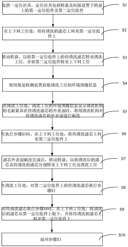
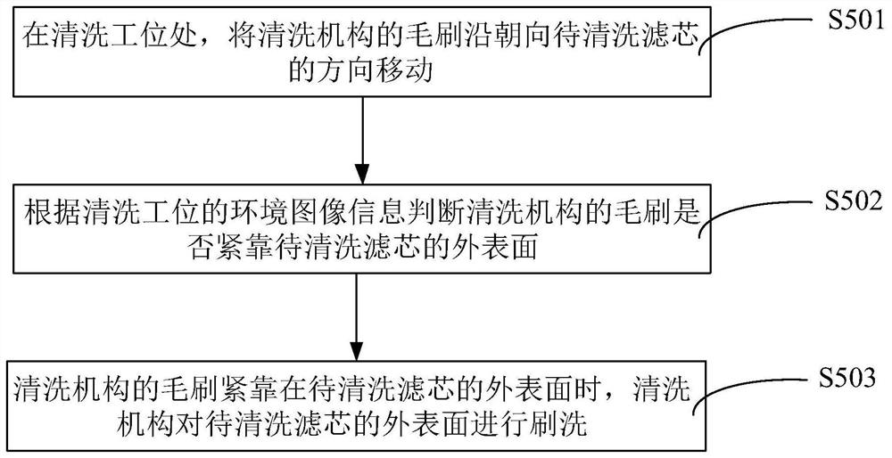
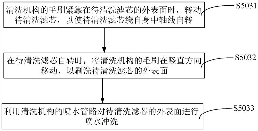
The invention relates to a filter element cleaning method based on visual inspection. The filter element cleaning method comprises the following steps: providing a positioning jig; on the feeding and discharging station, the to-be-cleaned filter element is fed to the first positioning assembly; rotating the turntable, and rotating the to-be-cleaned filter element to a cleaning station; acquiring environment image information of the cleaning station by utilizing a visual detection device; at the cleaning station, when a brush of the cleaning mechanism abuts against the outer surface of the to-be-cleaned filter element, the outer surface of the to-be-cleaned filter element is brushed through the cleaning mechanism; on the feeding and discharging station, the to-be-cleaned filter element is fed to the second positioning assembly; rotating the turntable, and respectively rotating the cleaned filter element and the to-be-cleaned filter element to a loading and unloading station and a cleaning station; scrubbing the filter element to be cleaned at the cleaning station; on the feeding and discharging station, the cleaned filter element is discharged, and the to-be-cleaned filter element is fed; and returning to execute the step of rotating the turntable, and rotating the filter element to be cleaned to the cleaning station. By using the filter element cleaning method, the cleaning efficiency and the cleaning effect in the batch cleaning process of the filter elements can be improved.

Description

technical field [0001] The invention relates to the technical field of filter element cleaning, in particular to a visual detection-based filter element cleaning method. Background technique [0002] The filter element refers to the ability to remove a small amount of impurities in the filter medium to purify the polluted medium, thereby protecting the normal operation of the equipment or ensuring the cleanliness of the air. It can filter oil, water and air, so it is widely used. For example, the filter element of the cutting fluid of the CNC machining center can prevent the debris, powder, mud, wire drawing flocs and other dirt after processing from blocking the chip fluid outlet, causing the temperature of the chip tool to rise, the product to be scrapped, and the tool to be damaged. The filter element is a hollow cylindrical welded part, with filter holes on the outer wall, and a layer of filter screen with higher density and smaller holes on the outer surface. The cuttin...

Claims


Application Information

Patent Timeline
IPC IPC(8): B08B1/02B08B3/02B08B13/00G01N21/84
CPCB08B1/002B08B1/02B08B3/022B08B3/024B08B13/00G01N21/84
Inventor 张成李群胜范京广王建军
Owner 湖南思博睿智能装备有限公司
Why Eureka
Try Eureka