
High-temperature flue gas heat energy recovery system

A technology of heat recovery and high-temperature flue gas, which is applied in the direction of indirect heat exchangers, heat exchanger types, heat exchange equipment, etc., can solve the problems that heat energy cannot be recycled, improve cleaning effect and efficiency, and improve heat exchange efficiency , improve the effect of consistency

Pending Publication Date: 2021-11-16
宁波晟光金属制品有限公司
View PDF0 Cites 0 Cited by
  • Summary
  • Abstract
  • Description
  • Claims
  • Application Information

AI Technical Summary

Problems solved by technology

[0004] This application provides a high-temperature flue gas heat energy recovery system, which is used to solve the problem that the heat energy in the high-temperature flue gas cannot be recycled in the prior art

Method used


Image

  • High-temperature flue gas heat energy recovery system
  • High-temperature flue gas heat energy recovery system

Examples


Embodiment Construction

[0025] The implementation manner of the present application will be further described in detail below with reference to the drawings and embodiments. The following examples are used to illustrate the present application, but cannot be used to limit the scope of the present application.

[0026] In the description of the embodiments of the present application, it should be noted that the terms "center", "vertical", "transverse", "upper", "lower", "front", "rear", "left", "right" , "vertical", "horizontal", "top", "bottom", "inner", "outer" and other indicated orientations or positional relationships are based on the orientations or positional relationships shown in the drawings, and are only for the convenience of describing this The application embodiments and simplified descriptions do not indicate or imply that the devices or elements referred to must have a specific orientation, be constructed and operated in a specific orientation, and therefore should not be construed as ...


PUM


Abstract

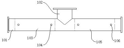
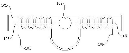
The invention discloses a high-temperature flue gas heat energy recovery system. The high-temperature flue gas heat energy recovery system comprises a gas inlet pipe and a gas outlet pipe, one end of the gas outlet pipe is fixedly connected with a position between the two ends of the gas inlet pipe, the gas outlet pipe communicates with the gas inlet pipe, a first partition plate is fixedly connected to the interior of the gas inlet pipe, the first partition plate is fixedly connected with a first heat exchange pipe, and the first heat exchange pipe is arranged in a snakelike mode along the central axis of the air inlet pipe. A cold medium is input into an inlet of the first heat exchange pipe, a hot medium is output from an outlet of the first heat exchange pipe, the cold medium becomes a hot medium after absorbing heat and is discharged from the outlet of the first heat exchange pipe, the outlet of the first heat exchange pipe is connected with a cleaning pool, water in the cleaning pool circularly flows through the first heat exchange pipe and absorbs the heat of high-temperature flue gas, recovery is carried out on the heat energy in the high-temperature flue gas, after the water in the cleaning pool is heated, sundries and oil stains adhered to the surface of a workpiece can be separated from the workpiece more quickly, and therefore the cleaning effect and the cleaning efficiency are improved.

Description

technical field [0001] The present application relates to the technical field of heat recovery, in particular to a high-temperature flue gas heat energy recovery system. Background technique [0002] In the manufacturing process of fasteners such as bolts and nuts, quenching and annealing processes are required. In order to improve the efficiency of quenching and annealing, it is usually used to pass through the quenching furnace and annealing furnace. The quenching furnace is equipped with a heater and a quenching liquid. (water or oil), put the workpiece on the conveyor belt, when the workpiece passes through the quenching furnace with the conveyor belt, it is heated first, and then enters to complete quenching, and after quenching, it goes through the annealing furnace with the conveyor belt to complete annealing. [0003] After the workpiece enters the quenching furnace, the workpiece is in contact with the air in the quenching furnace and a part of the heat is transferr...

Claims


Application Information

Patent Timeline
IPC IPC(8): F28D7/08F28F9/00F28F1/00
CPCF28D7/082F28F9/005F28F1/00
Inventor 何全德
Owner 宁波晟光金属制品有限公司
Learn More