Automatic measuring and abrasion cutting device for display production and manufacturing

An automatic measurement and display technology, applied in grinding drives, manufacturing tools, grinding machines, etc., can solve the problems of lack of clamping and positioning structure of conveyor belt, unfavorable workpiece processing, workpiece die-cutting, polishing shaking or jittering, etc.

Active Publication Date: 2021-11-26
江苏雅驹新材料实业有限公司
View PDF9 Cites 2 Cited by
  • Summary
  • Abstract
  • Description
  • Claims
  • Application Information

AI Technical Summary

Problems solved by technology

[0004] In order to solve the above-mentioned technical problems, the present invention provides an automatic measuring and grinding device for the production and manufacture of displays, to solve the problem of the conveyor belt after loading the conveyor belt when conveying the workpiece similar to the existing conveying equipment The lack of a clamping and positioning structure on the upper surface causes shaking or shaking of the workpiece during die-cutting and polishing, which is not conducive to the processing of the workpiece

Method used


Image

  • Automatic measuring and abrasion cutting device for display production and manufacturing
  • Automatic measuring and abrasion cutting device for display production and manufacturing
  • Automatic measuring and abrasion cutting device for display production and manufacturing

Examples


Embodiment

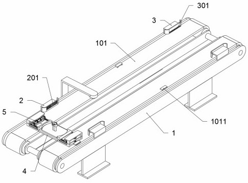
[0036] as attached figure 1 to attach Figure 10 Shown:

[0037] The present invention provides an automatic measuring and grinding device for the production and manufacture of displays, comprising a transmission frame 1, the left end of the frame body of the transmission frame 1 is fixedly connected with two fastening end frames 2, and the two fastening end frames 2 are respectively fixed Connected to the frame bodies on both sides of the transmission frame 1, the fastening end frame 2 includes a fastening rack 201, the fastening rack 201 is set on the inner surface of the fastening end frame 2, and the fastening rack 201 is located on the The upper part of the inner surface of the fastening end frame 2; the fastening end frame 2 of this structure is as figure 2 As shown; the translation positioning processing table 4 is movably connected above the transmission frame 1; the top tension frame 5 is provided with two places, and the two top tension frames 5 are respectively s...

Embodiment 2

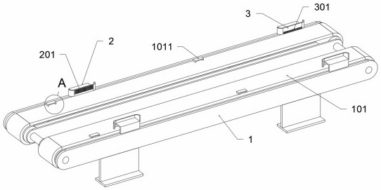
[0045] Embodiment 2: Based on the automatic measuring and grinding device for display manufacturing provided in the first embodiment, after the device clamps the workpiece, it realizes positioning and unloading. In order to eliminate the conflict between the clamping drive and the sending drive, combine figure 2 , the automatic measuring and grinding device for display production and manufacturing also includes: two unloading frames 3 are provided, the two unloading frames 3 are fixedly connected above the right end of the transmission frame 1, and the two unloading frames 3 They are respectively fixedly connected to the front side frame and the rear side frame body of the transmission frame 1. The loosening rack 3 includes a loosening rack 301, and the loosening rack 301 is set on the inner surface of the loosening rack 3, and the loosening rack 301 is located at the lower half of the inner surface of the unloading frame 3; the unloading frame 3 of this structure is as fig...

Embodiment 3

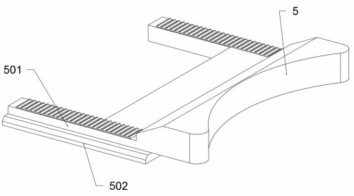
[0046] Embodiment 3: Based on the automatic measuring and grinding device for the production and manufacture of displays provided in the first embodiment, in order to facilitate the clamping of the clamping frame 5, the clamping frame 5 is set as an arc structure, which can better Clamp the display base in disc structure.

[0047] When in use: first, during the operation of the transmission frame 1, the display support is placed on the translation positioning processing table 4. When the translation positioning processing table 4 is running, it drives the translation positioning processing table 4 to move to the right. When the translation positioning processing table 4 When moving to the position of the fastening end frame 2, the fastening gear 403 meshes with the fastening rack 201, drives the fastening gear 403 to rotate counterclockwise, and then meshes with the clamping driven gear 701 through the fastening gear 403 to drive the fastening The worm 7 rotates, the fastening...


PUM


Abstract

The invention provides an automatic measuring and abrasion cutting device for display production and manufacturing, belongs to the technical field of display manufacturing equipment, and aims to solve the problems that when workpieces are conveyed by existing conveying equipment, after feeding is conducted on a conveying belt, the conveying belt is lack of a clamping and positioning structure, the workpieces shake or shake in the die cutting and polishing process, and workpiece machining is not facilitated. The automatic measuring and abrasion cutting device comprises a transmission frame, the left end of a frame body of the transmission frame is fixedly connected with two fastening end frames, and the two fastening end frames are fixedly connected to frame bodies at the two sides of the transmission frame respectively; and two loosening and unloading frames are included, the two loosening and unloading frames are fixedly connected to the upper portion of the right end of the transmission frame, and the two loosening and unloading frames are fixedly connected to a front side frame body and a rear side frame body of the transmission frame correspondingly. It can be seen that the structure is additionally arranged on a conveying mechanism, the functions of fixed-point clamping and fixed-point discharging are achieved, practice of automatic machining and production is facilitated, and the positioning stability of the workpieces when the workpieces are machined on a conveying device is improved.

Description

technical field [0001] The invention belongs to the technical field of display manufacturing equipment, and more specifically relates to an automatic measuring and grinding device for display manufacturing. Background technique [0002] The display is one of the hardware of the computer. In the existing display manufacturing, multiple parts are often spliced ​​together, and then assembled, fastened and inspected. When processing the base of the display, in order to improve the appearance of the display And assembly, the display base needs to be processed by cutting, grinding, polishing, shot blasting, etc.; in the existing display base processing workshop, most of the workpieces are transported by conveyor belts, and the moving workpieces participate in multiple processing steps. [0003] Based on the above, and in combination with the structure in the prior art, it is found that similar to the existing conveying equipment when conveying the workpiece, after loading the conv...

Claims


Application Information

Patent Timeline
Patent Type & Authority Applications(China)
IPC IPC(8): B24B19/00B24B29/02B24B27/06B24B41/02B24B41/06B24B41/00B24B47/00
CPCB24B19/00B24B29/02B24B27/0683B24B41/02B24B41/06B24B41/005B24B47/00
Inventor 贺玲
Owner 江苏雅驹新材料实业有限公司
Why Eureka
Try Eureka