Conveying line and control method
A conveyor line and controller technology, applied in the field of conveyor systems, can solve problems such as low efficiency, achieve the effect of reducing manual operations and improving product conveying efficiency
- Summary
- Abstract
- Description
- Claims
- Application Information
AI Technical Summary
Problems solved by technology
Method used
Image
Examples
Embodiment 1
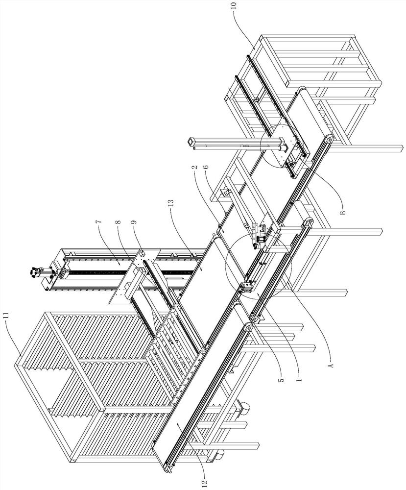
[0044] combined with Figure 1-5 , the present embodiment provides a conveying line, comprising:
[0045] Conveying assembly one 1 and conveying assembly two 2 arranged in sequence;
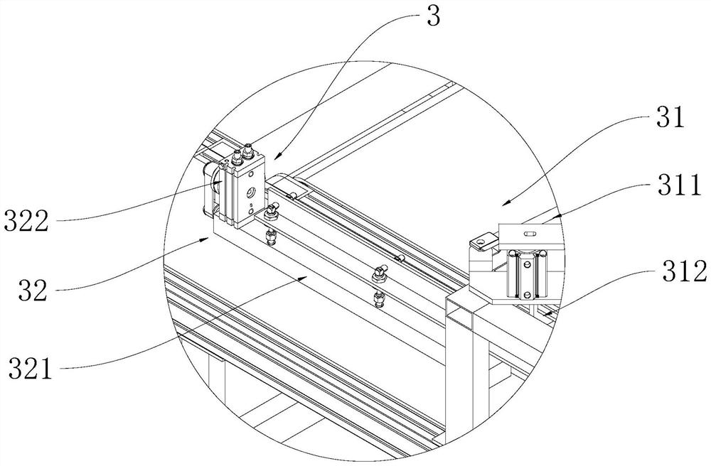
[0046] mobile unit one 31;
[0047] Adsorption force adjustable unit 1 32 connected with mobile unit 1 31;
[0048] mobile unit two 41;
[0049] Adsorption adjustable unit 2 42 connected with mobile unit 2 41;
[0050] sensor one 5;
[0051] sensor two 6;
[0052] Controller, controller and conveying component 1, conveying component 2 2, moving unit 1 31, adsorption force adjustable unit 1 32, moving unit 2 41, adsorption force adjustable unit 2 42, sensor 1 5 and sensor 2 6 connect.
[0053]Specifically, the conveying component-1 is used to transport the products processed by the equipment, such as brake pads sprayed by a laser inkjet printer, etc., and make the products be arranged one by one on the conveying component-1, and in order to prevent the equipment and the conveying component ...
Embodiment 2
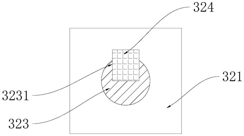
[0055] combined with Figure 1-5 , a kind of conveying line of the present embodiment, compared with the technical solution of embodiment 1, can be improved as follows: the adsorption force adjustable unit one 32 comprises the housing one 321 that is connected with the mobile unit one 31, the rotating element one 322 and with The shaft 323 connected to the first rotating element 322, one side of the shaft 323 is provided with a magnetic body 324, the shaft 323 is movably connected in the housing one 321, the rotating element one 322 is arranged on the housing one 321, the rotating element one 322 and the controller connect.
[0056] Specifically, when the casing one 321 is located at the conveying assembly one 1, the controller controls the rotating element one 322 to rotate, and the rotating element one 322 drives the shaft 323 to rotate, so that the side of the shaft 323 with the magnetic body 324 turns to the conveying assembly one 1, Thereby, the magnetism of the housing ...
Embodiment 3
[0059] combined with Figure 1-5 , a transmission line of this embodiment, compared with the technical solution of Embodiment 1 or 2, can be improved as follows: one side of the shaft 323 is provided with a groove 3231, and the magnetic body 324 is located in the groove 3231.
[0060] Specifically, the groove 3231 is used to accommodate the magnetic body 324 , and the groove 3231 is opened along the axial direction of the shaft 323 , which can effectively limit the radial movement of the magnetic body 324 to ensure the radial stability of the magnetic body 324 .
PUM
 Abstract
Description
Claims
Application Information
 - R&D Engineer
- R&D Manager
- IP Professional
- Industry Leading Data Capabilities
- Powerful AI technology
- Patent DNA Extraction
Browse by: Latest US Patents, China's latest patents, Technical Efficacy Thesaurus, Application Domain, Technology Topic, Popular Technical Reports.
© 2024 PatSnap. All rights reserved.Legal|Privacy policy|Modern Slavery Act Transparency Statement|Sitemap|About US| Contact US: help@patsnap.com


