Energy-gathering high-energy air flame heat energy stove

An energy gathering, high-energy technology, applied in the direction of household heating, heating fuel, household stove/stove, etc., can solve the problems of adjusting the way of flame spraying, fixed flame direction, inability to heat the pot, etc., to achieve enhanced strength, The effect of uniform heating and improved flame control

Inactive Publication Date: 2021-11-26
惠泽(吉林省)科技开发有限公司
View PDF0 Cites 0 Cited by
  • Summary
  • Abstract
  • Description
  • Claims
  • Application Information

AI Technical Summary

Problems solved by technology

[0003] At present, when using a controlled flame heat energy stove, the direction of the flame generated is fixed, and the pot cannot be heated according to the needs of cooking. At the same time, when the stove is in use, the flame size can only be adjusted simply, but it cannot be adjusted according to different cooking conditions. The method of adjusting the flame ejection for certain dishes makes it difficult to control the heat of cooking and cooking, which in turn affects the cooking of the dishes

Method used


Image

  • Energy-gathering high-energy air flame heat energy stove
  • Energy-gathering high-energy air flame heat energy stove
  • Energy-gathering high-energy air flame heat energy stove

Examples


Embodiment 1

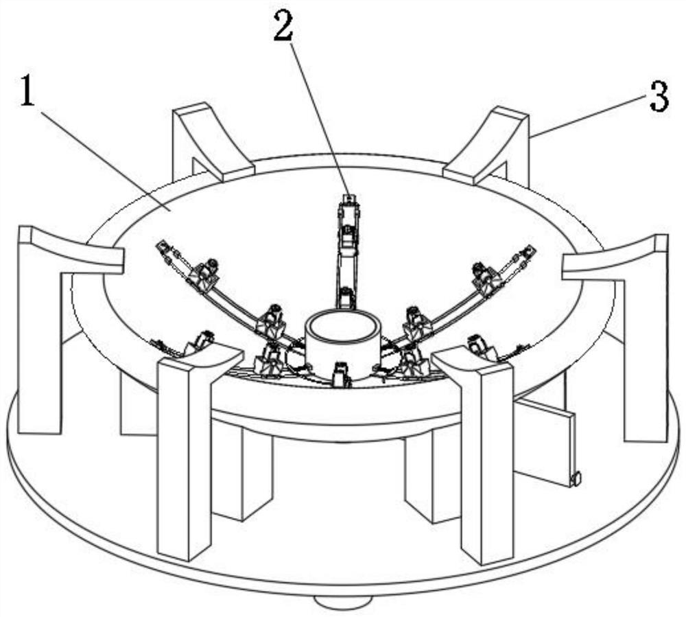
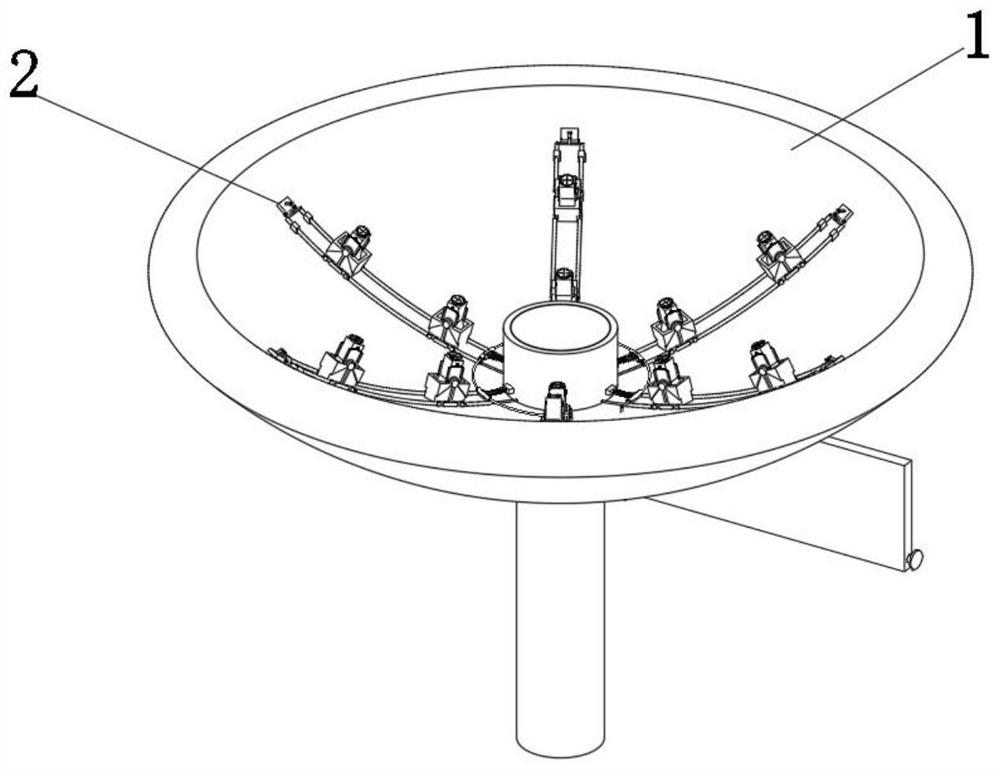
[0045] see Figure 1-Figure 9 As shown, a high-energy air flame thermal energy cooker with energy concentration is provided, including a spray cooker 1 and a flame regulator 2 arranged inside the spray cooker 1 for adjusting the flame. The bottom of the spray cooker 1 is provided with a useful The cooking stove rack 3 that supports the jet stove pan 1, the jet stove pan 1 includes an arc-shaped placement tray 11, the interior of the placement tray 11 is a hollow structure, and a central air outlet rack 13 is arranged at the middle position on the upper side of the placement tray 11. The side wall on the upper side of the placement tray 11 is arranged in a circular arrangement with several tie rod stoppers 17, and the several tie rod stoppers 17 provided are arranged in multiple turns, and the tie rod stoppers 17 of the inner ring and the outer ring are arranged corresponding to each other, and the flame Regulator 2 comprises several driving devices 21, one side of driving devi...

Embodiment 2

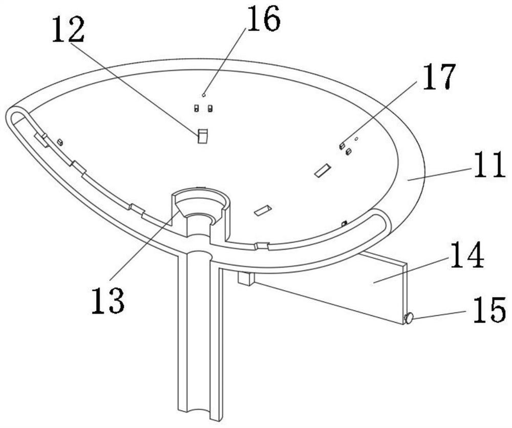
[0059] In order to control the flame on the edge of the tray 11, so that the edge of the pot is heated by the flame on the edge of the tray 11, refer to Figure 10 The edge controller 24 corresponding to the flame angle adjusting device 22 is arranged in a circular arrangement near the edge on the upper side of the placement tray 11. The edge controller 24 includes two sliding rods 241 hinged with the belt 225, and the two sliding rods 241 One end is fixed with a fixed frame 242, and one end of the fixed frame 242 is provided with a cover plate 243 hinged on the upper side of the placement tray 11, and the upper side of the placement tray 11 is arranged in a circular arrangement near the edge to provide edge fire outlets 16, and the bottom of the cover plate 243 The plunger that will block the edge fire outlet 16 is set, the oblique rod 244 that is arranged obliquely is fixed on the cover plate 243, the oblique rod 244 and the fixed frame 242 are connected by a hinged hinge rod...


PUM


Abstract

The invention relates to a high-energy air flame heat energy stove, in particular to an energy-gathering high-energy air flame heat energy stove. The energy-gathering high-energy air flame heat energy stove comprises a jet stove plateand a flame regulator,the flame regulator is arranged in the jet stove plate and is used for regulating flame, and the bottom of the jet stove plate is provided with a cooking stove placing frame for supporting the jet stove plate. While a turner rotates to adjust the angle, the flame regulator synchronously controls flames, and when the turner rotates towards the direction close to a central gas outlet frame, the flame regulator gathers the flames, so that the flames ejected from the turner are ejected into the flames ejected from the central gas outlet frame, the strength of the central flames is enhanced. When the turner rotates in the direction far away from the central air outlet frame, the flame regulator shunts flame, so that the flame jetted in the turner is uniformly diffused to the periphery, and the flame uniformly cooks dishes needing to be fried.

Description

technical field [0001] The invention relates to a high-energy air flame heat cooker, in particular to an energy-gathering high-energy air flame heat cooker. Background technique [0002] The air flame heat energy stove is based on the widely used principle of plasma flame generation, and its circuit and structure have been newly designed and boldly invented and innovated. It is designed and intelligently managed through clustered capacitors and shunt circuits to quickly and uniformly generate high voltage. Accurately pierces the air and creates flames. [0003] At present, when using a controlled flame heat energy stove, the direction of the flame generated is fixed, and the pot cannot be heated according to the needs of cooking. At the same time, when the stove is in use, the flame size can only be adjusted simply, but it cannot be adjusted according to different cooking conditions. Some dishes adjust the way the flame is ejected, which makes it impossible to control the h...

Claims


Application Information

Patent Timeline
Patent Type & Authority Applications(China)
IPC IPC(8): F24C7/08F24C15/10
CPCF24C7/082F24C15/10
Inventor 不公告发明人
Owner 惠泽(吉林省)科技开发有限公司
Why Eureka
Try Eureka