Camera module with protection device

A camera module and protection device technology, applied in image communication, camera body, color TV components and other directions, can solve the problems of lack of protective measures, affecting the service life of the camera module, distribution, etc., to achieve easy protection, The effect of improving the range of use and being easy to disperse

Pending Publication Date: 2021-11-26
江西百宏光电科技有限公司
View PDF3 Cites 2 Cited by
  • Summary
  • Abstract
  • Description
  • Claims
  • Application Information

AI Technical Summary

Problems solved by technology

When the existing camera modules are embedded in the electronic equipment, they are often exposed inside the electronic equipment without protective measures, which will cause the heat generated inside the electronic equipment to be dissipated into the camera module, thereby affecting the performance of the camera module. service life

Method used


Image

  • Camera module with protection device
  • Camera module with protection device
  • Camera module with protection device

Examples


Embodiment 1

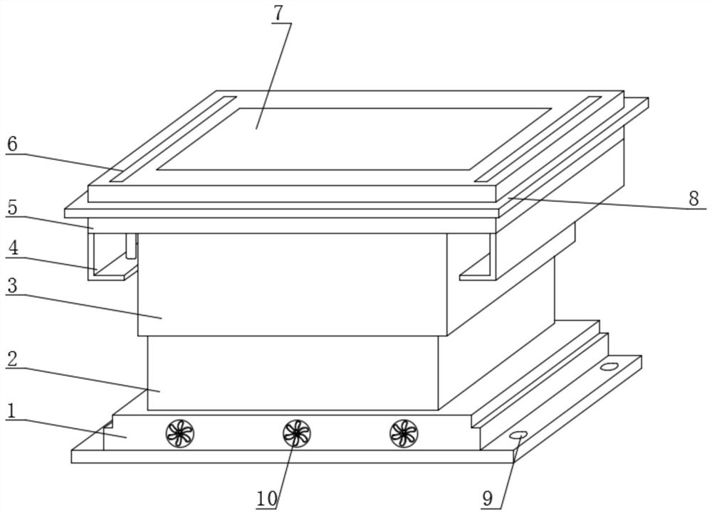
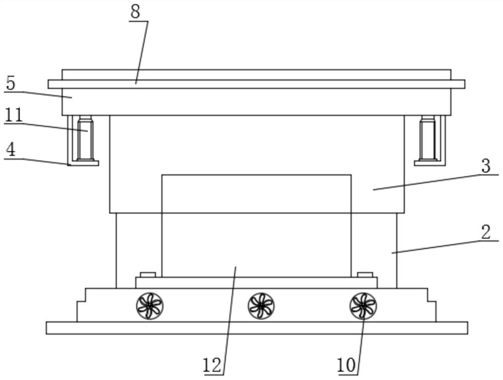
[0035] Embodiment one, with reference to figure 1 , 2 , 4, 5, 7 and Figure 8 , a camera module with a protective device, comprising a mounting base 1, a lower protective cover 2 is provided on the top surface of the mounting base 1, an upper protective cover 3 is arranged above the lower protective cover 2, and the upper protective cover 3 The top is provided with a top plate 5, and the bottom end of the upper protective cover 3 is provided with a movable groove 15, and the lower protective cover 2 is clamped inside the movable groove 15, and the top of the upper protective cover 3 is provided with a spring 18, and the spring 18 The top is provided with a sliding frame 17, and the camera module assembly 12 is installed on the top surface of the installation base 1. After the camera module assembly 12 is installed on the installation base 1, the staff installs the upper protective cover 3 to the lower protective cover through the top plate 5. Cover 2, so that the lower prote...

Embodiment 2

[0036] Embodiment two, refer to figure 1 and Figure 6 , the top surface of the installation base 1 is provided with a cooling cavity 20, the top of the cooling cavity 20 is provided with a grille 16, the surface of the installation base 1 is equipped with a cooling fan 10, and the cooling fan 10 is provided with a plurality of Two radiating fans 10 are equidistantly installed on the outer surface of the mounting base 1, by setting the radiating chamber 20, the grille 16 and the radiating fan 10 in cooperation, when in use, the camera module assembly 12 is installed on the top surface of the grille 16, thereby The heat generated by the camera module assembly 12 enters the heat dissipation chamber 20 through the grille 16, and finally dissipates through the heat dissipation fan 10. This method is easy to operate, and is convenient for dissipating the heat generated by the camera module assembly 12, preventing it from being dissipated. The protective cover is blocked and cannot...

Embodiment 3

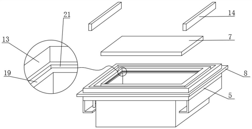
[0037] Embodiment three, refer to figure 1 and image 3, the surface of the top plate 5 is provided with an insertion groove 6, and a rubber block 14 is inserted inside the insertion wiper, the bottom end of the top plate 5 is provided with a mounting frame 4, and the top of the mounting frame 4 is provided with an electric push rod 11. The top end of the electric push rod 11 is connected to the bottom end of the rubber block 14, and the middle position of the surface of the top plate 5 is provided with an installation groove 13, and the inside of the installation groove 13 is provided with a bearing platform 19, and the inside of the installation groove 13 is provided with There is a protective shell 7, the top surface of the bearing platform 19 is provided with a pouring groove 21, the installation groove 13 and the protective shell 7 are interference fit, and there are two insertion grooves 6, and the two insertion grooves 6 are symmetrical It is installed on the surface o...


PUM


Abstract

The invention discloses a camera module with a protection device, which comprises a mounting base, a lower protective cover is arranged on the top surface of the mounting base, an upper protective cover is arranged above the lower protective cover, a top plate is arranged at the top of the upper protective cover, and a movable groove is formed in the bottom end of the upper protective cover. Through cooperative use of the upper protective cover, the lower protective cover and the top plate, protection of the camera module assembly is facilitated, meanwhile, a movable groove is formed in the bottom end of the upper protective cover, and after the camera module assembly is installed on the installation base, a worker installs the upper protective cover on the lower protective cover through the top plate, so that the lower protective cover is inserted into the movable groove, and the camera module assembly is protected. The method is easy to operate, the situation that a traditional camera module assembly is installed in the electronic equipment in an exposed mode is changed, and the camera module assembly is prevented from being affected by heat generated in the electronic equipment.

Description

technical field [0001] The invention relates to the technical field of camera module protection, in particular to a camera module with a protection device. Background technique [0002] The camera module is an important part of the camera. It is composed of various parts. The bracket in the base structure of the camera module is mainly used to fix the PCB board, the filter adjustment motor and other parts. It is an indispensable part of the camera module. With the advancement of science and technology, camera modules are increasingly used in electronic products, such as notebook computers and mobile phones. When the existing camera modules are embedded in the electronic equipment, they are often exposed inside the electronic equipment without protective measures, which will cause the heat generated inside the electronic equipment to be dissipated into the camera module, thereby affecting the performance of the camera module. service life. [0003] Aiming at the problems in...

Claims


Application Information

Patent Timeline
IPC IPC(8): H04N5/225G03B17/55
CPCG03B17/55H04N23/57H04N23/51Y02E40/30
Inventor 李亚鹏涂金汉许赐春
Owner 江西百宏光电科技有限公司
Why Eureka
Try Eureka