Landscaping engineering tree soil ball excavation and maintenance equipment

A landscaping and equipment maintenance technology, applied in the field of landscaping, can solve the problems of soil secondary drop, trees unable to absorb nutrient solution, soil damage, etc., to avoid secondary damage, shorten the sealing time, and improve the survival rate Effect

Active Publication Date: 2021-11-30
江苏千叶建设有限公司
View PDF25 Cites 8 Cited by
  • Summary
  • Abstract
  • Description
  • Claims
  • Application Information

AI Technical Summary

Problems solved by technology

[0002] In the prior art, in the process of using the arc knife tree digging machine, the vibrating arc knife is used to penetrate into the ground to cut and separate the roots and soil layer below the tree, but when the arc knife completes the cutting of the soil ball at the bottom of the tree Finally, it is necessary to control the reverse rotation of the circular arc knife to the middle of the bottom of the soil ball, that is, the secondary damage to the soil at the bottom of the soil ball is formed during the reverse rotation of the circular arc knife, and at the same time, the circular arc knife is used to lift the soil ball upwards At the same time, the vibration force of the arc knife and the upward support force will cause the soil at the bottom of the soil ball to fall again, and the partially cracked soil at the bottom of the soil ball will also fall, causing the soil ball to split and fall during the cutting and lifting process. Too much, and when the nutrient solution is sprayed on the surface of the soil ball after excavation, the top of the soil ball is covered with a layer of dead leaves, which prevents the nutrient solution from penetrating into the soil ball, and the roots of the tree cannot absorb the nutrient solution

Method used


Image

  • Landscaping engineering tree soil ball excavation and maintenance equipment
  • Landscaping engineering tree soil ball excavation and maintenance equipment
  • Landscaping engineering tree soil ball excavation and maintenance equipment

Examples


Embodiment 1

[0031] according to figure 1As shown, a tree soil ball excavation and maintenance equipment for landscaping engineering includes a tree digging head system 1, a tree body fixed maintenance system 2 and a soil ball top maintenance system 3; The fixed maintenance system 2 for the tree body; the left and right parts of the tree excavator head system 1 are each equipped with a soil ball top maintenance system 3 .

[0032] When in use, first fix the digging and maintenance equipment for landscaping engineering tree soil balls to the head of the tree digging machine, then start the tree digging machine to move to the side of the tree to be excavated, and then control the tree digging machine to move the tree digging machine head System 1 circles to the side of the tree, then controls the tree digging machine to start running, controls the tree body fixing maintenance system 2 to fix the tree, fixes the soil ball cloth to the tree digging head system 1, and then controls the tree dig...

Embodiment 2

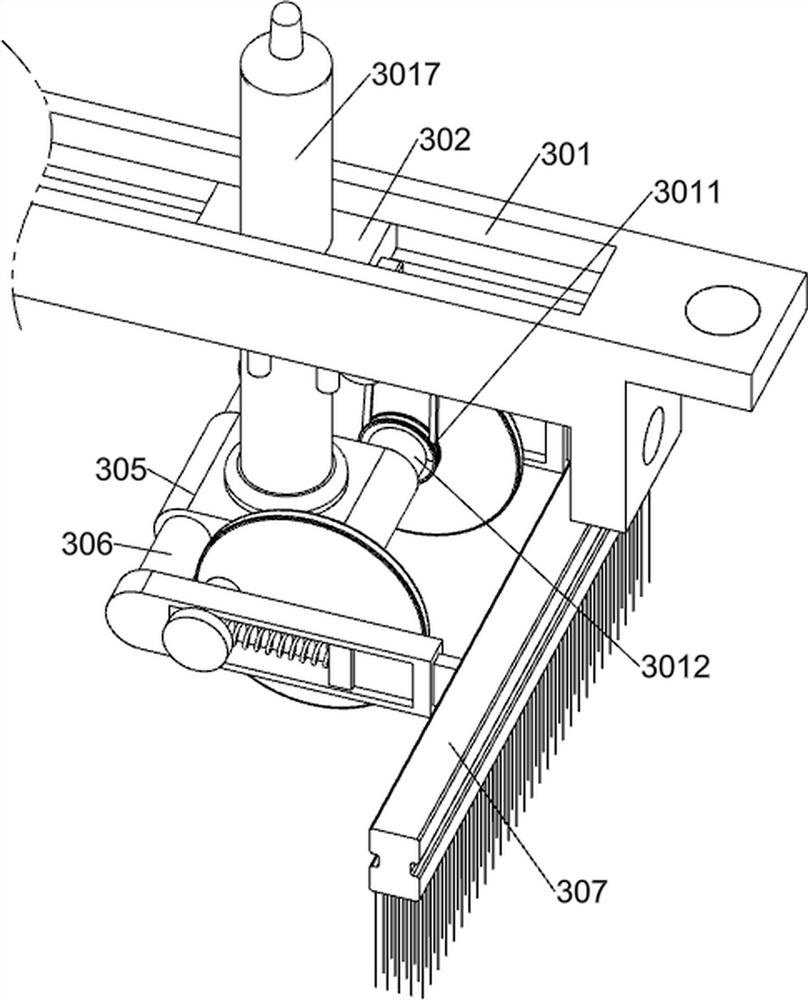
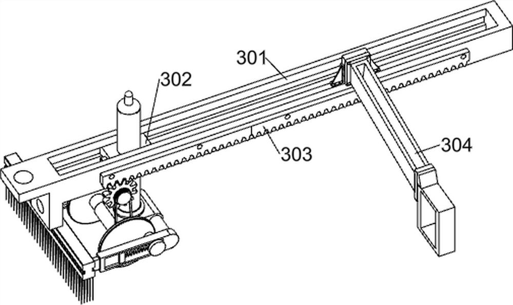
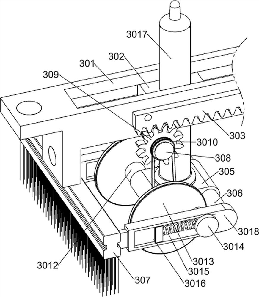
[0034] On the basis of Example 1, according to Figure 2-4 As shown, the tree-digging machine head system 1 includes an installation base 101, a universal coupling 102, a first installation side frame 103, a connecting seat 104, a fixed L-shaped frame 105, a fixed post 106, a vibration motor 107, and an excavator. Cutter head assembly, blower 1012, liquid spray pipe 1013, installation axle seat 1014 and electric clamp 1015; Installation base 101 left side bolt is connected with first installation side frame 103; First installation side frame 103 is rotatably connected with universal joint Shaft 102; the top front side bolt of the first installation side frame 103 is connected with a connection seat 104; the upper part of the first installation side frame 103 is fixedly inserted with a fixed L-shaped frame 105; the left front side of the connection seat 104 is fixedly inserted with a fixed post 106 The vibration motor 107 is installed on the inside of the fixed post 106; the bo...

Embodiment 3

[0043] On the basis of Example 2, according to figure 1 and Figure 5-6 As shown, the tree body fixed maintenance system 2 includes a mounting frame 201, a middle part cleaning assembly and a clamping assembly; the upper rear middle part of the fixed L-shaped frame 105 is bolt-connected with the mounting frame 201; the middle part of the mounting frame 201 is equipped with a middle part cleaning assembly; The front portion of the frame 201 is equipped with a clamping assembly.

[0044] Before the tree is dug, the clamping assembly can be controlled to fix the tree, and after the tree is dug, the middle cleaning assembly can be controlled to clean and separate the dead leaves on the rear side of the top surface of the soil ball.

[0045] The clamping assembly includes a second electric push rod 207, a third electric push rod 208, a first connecting rod 209, a second connecting rod 2010, a first semicircular splint 2011 and a second semicircular splint 2012; the left front part...


PUM


Abstract

The invention relates to the field of landscaping, in particular to landscaping engineering tree soil ball excavation and maintenance equipment. The technical problem that in the using process of an arc cutter tree mover in the prior art, soil at the bottom of a soil ball is secondarily damaged in the reverse rotation process of an arc cutter is solved. According to the technical scheme, the landscaping engineering tree soil ball excavation and maintenance equipment comprises a tree excavation machine head system, a tree body fixing and maintaining system and a soil ball top maintaining system; and a tree body fixing and maintaining system is installed on the rear middle part of the upper side of the tree mover head system. According to the landscaping engineering tree soil ball excavation and maintenance equipment, soil ball cloth is wrapped at the bottom of the soil ball while the soil ball is cut, the cracked soil at the bottom of the soil ball cannot fall off and be separated, dead leaves at the top of the soil ball are automatically cleaned after the soil ball is excavated out, so that a nutrient solution can permeate into the soil, the exposure time of a root system in the air is shortened, and the transplanting survival rate is improved.

Description

technical field [0001] The invention relates to the field of landscaping, in particular to a tree soil ball digging and maintenance device for landscaping engineering. Background technique [0002] In the prior art, in the process of using the arc knife tree digging machine, the vibrating arc knife is used to penetrate into the ground to cut and separate the roots and the soil layer below the tree, but when the arc knife completes cutting the soil ball at the bottom of the tree Finally, it is necessary to control the reverse rotation of the circular arc knife to the middle of the bottom of the soil ball, that is, the secondary damage to the soil at the bottom of the soil ball is formed during the reverse rotation of the circular arc knife, and at the same time, the circular arc knife is used to lift the soil ball upwards At the same time, the vibration force of the arc knife and the upward support force will cause the soil at the bottom of the soil ball to fall again, and th...

Claims


Application Information

Patent Timeline
Patent Type & Authority Applications(China)
IPC IPC(8): A01G23/06
CPCA01G23/06
Inventor 徐金龙
Owner 江苏千叶建设有限公司
Why Eureka
Try Eureka