Efficient silage cleaning equipment for feed production
A technology for cleaning equipment and silage, which is applied in the field of high-efficiency cleaning equipment for silage for feed production, can solve the problems of poor cleaning effect, large workload and low cleaning efficiency, and achieves improved effect, good effect, and improved cleaning effect. Effect
- Summary
- Abstract
- Description
- Claims
- Application Information
AI Technical Summary
Problems solved by technology
Method used
Image

Examples
Embodiment 1
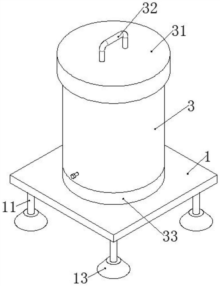
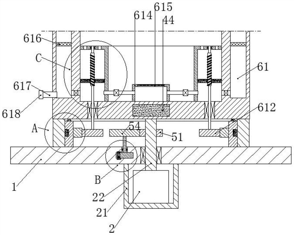
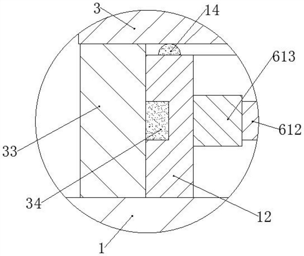
[0033] A high-efficiency cleaning equipment for silage used in feed production, including a pedestal 1, a driving motor 2, a cleaning cylinder 3, a floating seat 4, and an intermittent power supply device; An annular swivel seat 12 is affixed, the lower surface of the pedestal 1 is affixed to the machine cover 21, the drive motor 2 is fixed in the hood 21, the drive motor 2 is provided with a vertically upward output shaft 22, and the output shaft 22 is connected to the pedestal 1 Rotate connection, the top of the cleaning cylinder 3 is open, the top of the cleaning cylinder 3 is provided with a cover 31, the cover 31 is fixed with a U-shaped handle 32, the bottom plate of the cleaning cylinder 3 is fixedly connected with the top of the output shaft 22, The bottom of the cleaning cylinder 3 is affixed with a rotary sleeve 33, the inner ring of the rotary sleeve 33 is affixed with an annular slider 34, and the outer ring of the swivel base 12 is provided with a chute correspondi...
Embodiment 2
[0041] The difference from Example 1 is that it also includes the following:
[0042] The intermittent energization device includes a driving gear 51 and a turntable 52; the driving gear 51 is fixedly connected to the output shaft 22 between the pedestal 1 and the cleaning cylinder 3, the turntable 52 is rotatably connected in the pedestal 1, and the center of the upper surface of the turntable 52 is fixed with a shaft Rod 53, the top of the shaft rod 53 is fixedly connected with a driven gear 54 meshing with the driving gear 51, a 1 / 2 arc-shaped conductive plate 55 is fixedly connected on the turntable 52, and the pedestal 1 on the upper and lower sides of the turntable 52 is fixedly connected There are connecting boards 56, and the electromagnet 44 forms a series circuit with an external power supply through two connecting boards 56.
[0043] Preferably, the gear ratio of the driven gear 54 to the driving gear 51 is 3:1.
[0044] In this example:
[0045] When the driving ...
Embodiment 3
[0048] The difference from Example 2 is that it also includes the following:
[0049] The curved side plate of the cleaning cylinder 3 is provided with a water chamber 61, the top circumference of the water chamber 61 is uniformly provided with a water spray hole 62, and the bottom circumference of the water chamber 61 is uniformly provided with a drainage hole 63, and the bottom of the inner wall of the cleaning cylinder 3 is also fixed. An annular pump chamber 64 is connected, and an annular piston plate 65 is sealed and slidably connected in the pump chamber 64. The top of the pump chamber 64 is provided with a communication hole 66, and the circumference of the pump chamber 64 near the inner cavity of the cleaning cylinder 3 is evenly fixed with a The suction pipe 67, the drainage hole 63 and the suction pipe 67 are respectively provided with a first one-way valve 68 and a second one-way valve 69. The direction that the first one-way valve 68 allows fluid to pass is the dir...
PUM
 Abstract
Description
Claims
Application Information
 - R&D Engineer
- R&D Manager
- IP Professional
- Industry Leading Data Capabilities
- Powerful AI technology
- Patent DNA Extraction
Browse by: Latest US Patents, China's latest patents, Technical Efficacy Thesaurus, Application Domain, Technology Topic.
© 2024 PatSnap. All rights reserved.Legal|Privacy policy|Modern Slavery Act Transparency Statement|Sitemap