
Stamping manipulator

A technology of manipulators and servo motors, applied in the field of manipulators, can solve the problems of reduced practicability, easy compression of the second spring, and non-adjustable spacing, so as to prevent the workpiece from slipping, clamp tightly, and improve practicability

Pending Publication Date: 2021-11-30
李书阳
View PDF1 Cites 0 Cited by
  • Summary
  • Abstract
  • Description
  • Claims
  • Application Information

AI Technical Summary

Problems solved by technology

[0004] The above-mentioned comparative patent makes the movable frame move inwardly through the movement of the moving block under the action of the inclined plane and the rollers. The movement of the movable frame can drive the clamping block to perform synchronous movement, and the moving clamping block can thus move the workpiece under the action of the adjusting plate. Clamping is carried out to realize the loading and unloading operation of the workpiece by the manipulator, but because the distance between the two sets of moving blocks and the two sets of movable frames in the comparison patent is not adjustable, the device cannot be applied to the loading and unloading operations of workpieces of different sizes, reducing The practicability of the device is improved. In addition, the device avoids wear on the surface of the workpiece due to excessive clamping force by setting a buffer mechanism. However, due to the lack of a limit device to limit the buffer mechanism, the workpiece is transported. Second, the spring is prone to compression, resulting in insufficient clamping force of the splint on the workpiece, causing the workpiece to slip off, thus causing damage to the workpiece.

Method used


Image

  • Stamping manipulator
  • Stamping manipulator
  • Stamping manipulator

Examples


Embodiment Construction

[0038] The following will be combined with the present invention to realize some embodiments of the present invention, rather than all embodiments. Based on the embodiments of the present invention, all other embodiments obtained by persons of ordinary skill in the art without making creative efforts belong to the protection scope of the present invention.

[0039] In describing the present invention, it is to be understood that the terms "center", "longitudinal", "transverse", "length", "width", "thickness", "upper", "lower", "front", " Back", "Left", "Right", "Vertical", "Horizontal", "Top", "Bottom", "Inner", "Outer", "Clockwise", "Counterclockwise", etc. or The positional relationship is based on the orientation or positional relationship shown in the drawings, which is only for the convenience of describing the present invention and simplifying the description, rather than indicating or implying that the referred device or element must have a specific orientation, be cons...


PUM


Abstract

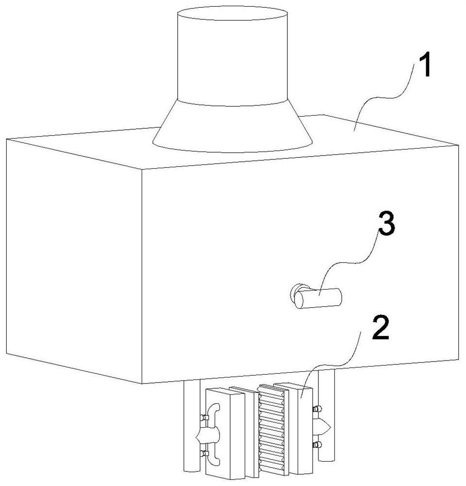
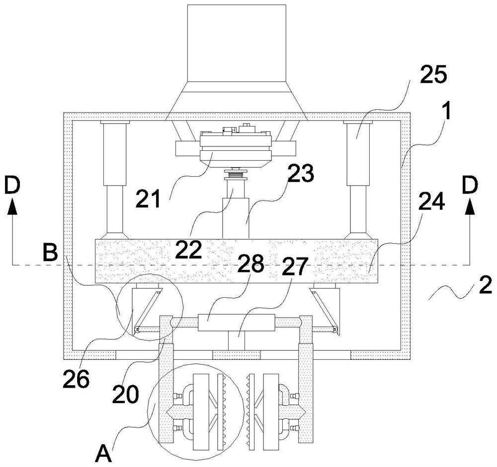
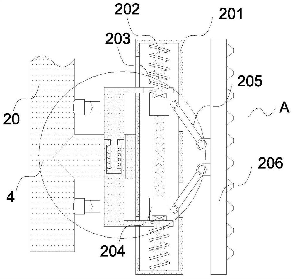
The invention discloses a stamping manipulator which comprises a fixing box. A clamping mechanism is fixedly connected to the interior of the fixing box, the clamping mechanism comprises a servo motor, a first screw rod, a first screw sleeve, a transverse plate, a positioning column, moving blocks, a first fixing rod, a sleeve, a first spring, movable frames, a fixing plate, a second fixing rod, a second spring, a sliding sleeve, a connecting rod and a clamping plate, and the servo motor is fixedly connected with the center position of the top end of the inner surface of the fixing box. By arranging an adjusting mechanism, the distance between the two sets of moving blocks and the distance between the two sets of movable frames can be adjusted by controlling rotation of a rotating handle, so that the stamping manipulator can be suitable for feeding and discharging operation of workpieces of different sizes, and the practicability of the stamping manipulator is improved; and by arranging a limiting mechanism, a limiting rod is fixed, the second spring cannot be compressed, clamping between the clamping plate and the workpieces is tighter, and the situation that the workpieces are damaged due to the fact that the workpieces slip off is prevented.

Description

technical field [0001] The invention relates to the technical field of manipulators, in particular to a stamping manipulator. Background technique [0002] With the development of society, people pay more and more attention to energy saving and environmental protection, and new energy is continuously utilized. However, when processing new energy motor rotors, stamping operations are required. In order to improve the work efficiency of stamping work, usually The manipulator is used instead of manual operation. The stamping manipulator is based on the automation equipment and according to the characteristics of stamping production, it is specially developed for the realization of stamping automation and unmanned production. It can replace manual work on material stamping, handling, loading and unloading at each stamping station. [0003] The Chinese patent discloses a new energy motor rotor stamping manipulator device, the patent application number is CN202021393451.3, which ...

Claims


Application Information

Patent Timeline
Patent Type & Authority Applications(China)
IPC IPC(8): B21D43/10B21D45/02
CPCB21D43/105B21D45/02
Inventor 李书阳丁昆浩
Owner 李书阳
Learn More