Automatic singeing device for knitted fabric
An automatic technology for knitted fabrics, applied in the field of knitted fabrics, can solve the problems that the device cannot be placed stably and the singeing efficiency is low, and achieve good singeing effect, high singeing efficiency, and improved use effect
- Summary
- Abstract
- Description
- Claims
- Application Information
AI Technical Summary
Problems solved by technology
Method used
Image
Examples
Embodiment 1
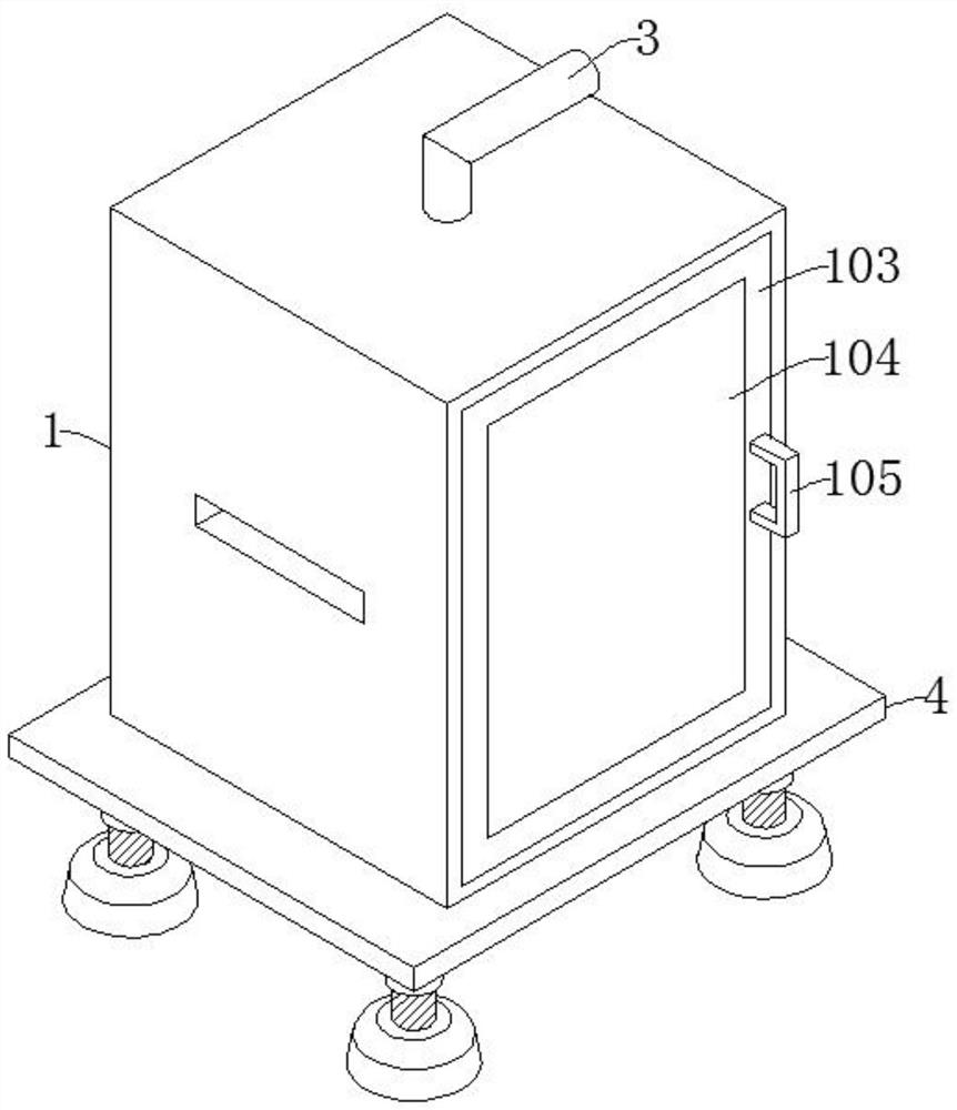
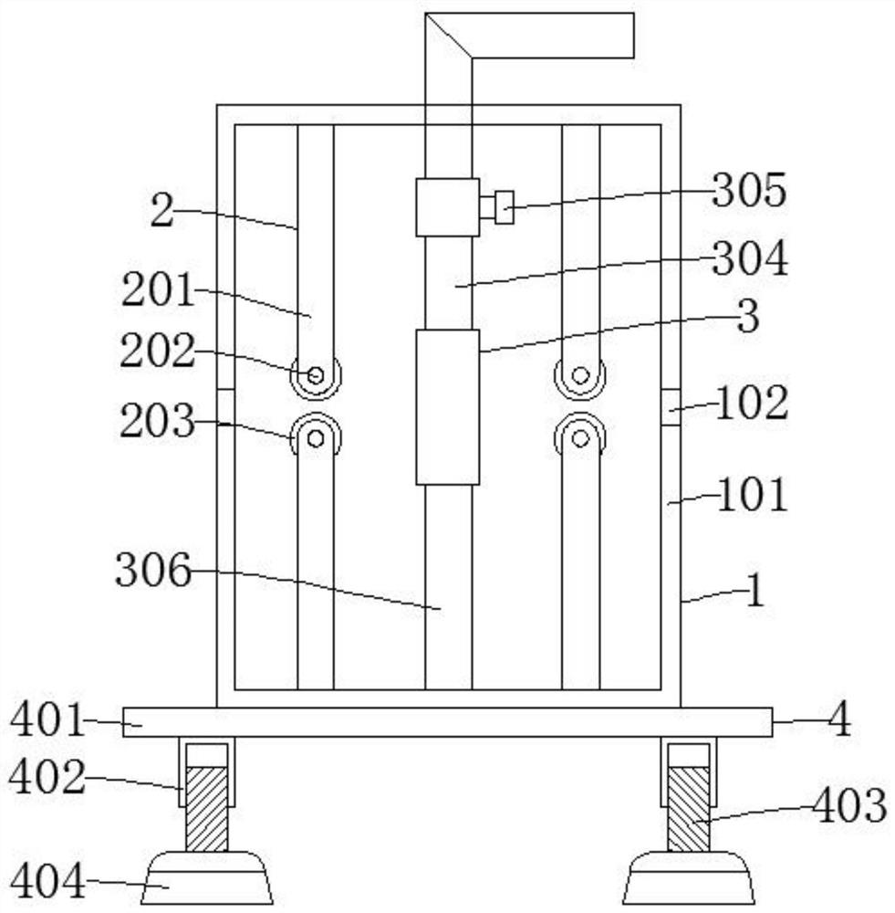
[0028] Such as figure 1 , image 3 , Figure 5 As shown, the knitted fabric automatic singeing device includes a closing mechanism 1 and a conveying mechanism 2. The conveying mechanism 2 is installed inside the closing mechanism 1. The number of conveying mechanisms 2 is four, and also includes a singeing mechanism 3 and a supporting mechanism 4. The wool mechanism 3 is arranged between the four conveying mechanisms 2, and the support mechanism 4 is fixed below the closing mechanism 1.
[0029] Closing mechanism 1 comprises closed box 101, through hole 102, chamber door 103, observation window 104, handle 105, is provided with through hole 102 on closed box 101, and box door 103 is installed on the box door 103, and box door 103 is equipped with Observation window 104, door 103 front portion is fixed with handle 105; Conveying mechanism 2 comprises connecting rod 201, rotating shaft 202, conveying roller 203, and the quantity of connecting rod 201 is two, and rotating shaft...
Embodiment 2
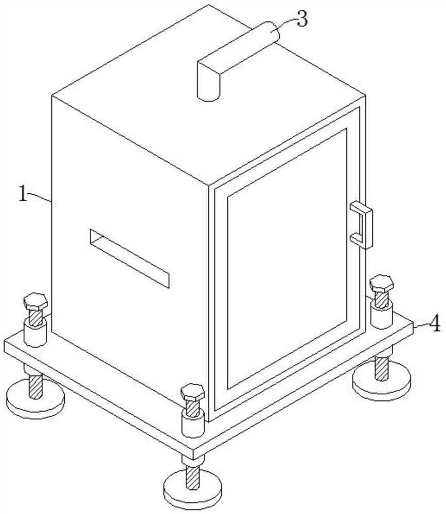
[0032] Such as figure 2 , Figure 4 , Figure 5 As shown, the difference between Embodiment 2 and Embodiment 1 is that the threaded barrel 402, the first threaded rod 403, and the base 404 are replaced by a threaded sleeve 405, a second threaded rod 406, an adjustment knob 407, a base plate 408, and the base plate 408 is connected with the adjustment The knob 407 is welded, and the thickness of the bottom plate 408 is 2cm. When using the device, place the device on the ground. When the ground is uneven, the second threaded rod 406 is driven to rotate by the adjustment knob 407. The second threaded rod 406 acts on the threaded sleeve 405. The bottom plate 408 is driven up and down to adjust the height of the four corners of the horizontal plate 401, so that the device can be stably placed on the ground.
PUM
 Abstract
Description
Claims
Application Information
 - R&D
- Intellectual Property
- Life Sciences
- Materials
- Tech Scout
- Unparalleled Data Quality
- Higher Quality Content
- 60% Fewer Hallucinations
Browse by: Latest US Patents, China's latest patents, Technical Efficacy Thesaurus, Application Domain, Technology Topic, Popular Technical Reports.
© 2025 PatSnap. All rights reserved.Legal|Privacy policy|Modern Slavery Act Transparency Statement|Sitemap|About US| Contact US: help@patsnap.com


