Electromagnetic braking cooperation mechanism self-locking navigation inertial unit transposition locking mechanism

An electromagnetic braking and locking mechanism technology, which is applied in control components, mechanical control devices, control/adjustment systems, etc., can solve the problem that the gear plate of the mechanism is stuck and the test cannot be continued, the state of the mechanism cannot be switched freely, and the error of the mechanism test is large, etc. problem, to achieve the effect of improving test stability, reducing the size of the outer envelope, and fast response

Active Publication Date: 2021-11-30
CHANGCHUN INST OF OPTICS FINE MECHANICS & PHYSICS CHINESE ACAD OF SCI
View PDF12 Cites 2 Cited by
  • Summary
  • Abstract
  • Description
  • Claims
  • Application Information

AI Technical Summary

Problems solved by technology

[0008] The purpose of the present invention is to propose a navigation inertial group indexing and locking mechanism with self-locking electromagnetic braking cooperative mechanism, so as to solve the problems in the prior art that the gear plate of the mechanism is stuck and cannot continue testing, the failure rate is high, and the error of the mechanism test is relatively large And the problem that the mechanism state cannot be switched freely and the test efficiency is low

Method used


Image

  • Electromagnetic braking cooperation mechanism self-locking navigation inertial unit transposition locking mechanism
  • Electromagnetic braking cooperation mechanism self-locking navigation inertial unit transposition locking mechanism
  • Electromagnetic braking cooperation mechanism self-locking navigation inertial unit transposition locking mechanism

Examples


Embodiment Construction

[0048] Embodiments of the present invention will be further described below in conjunction with the accompanying drawings.

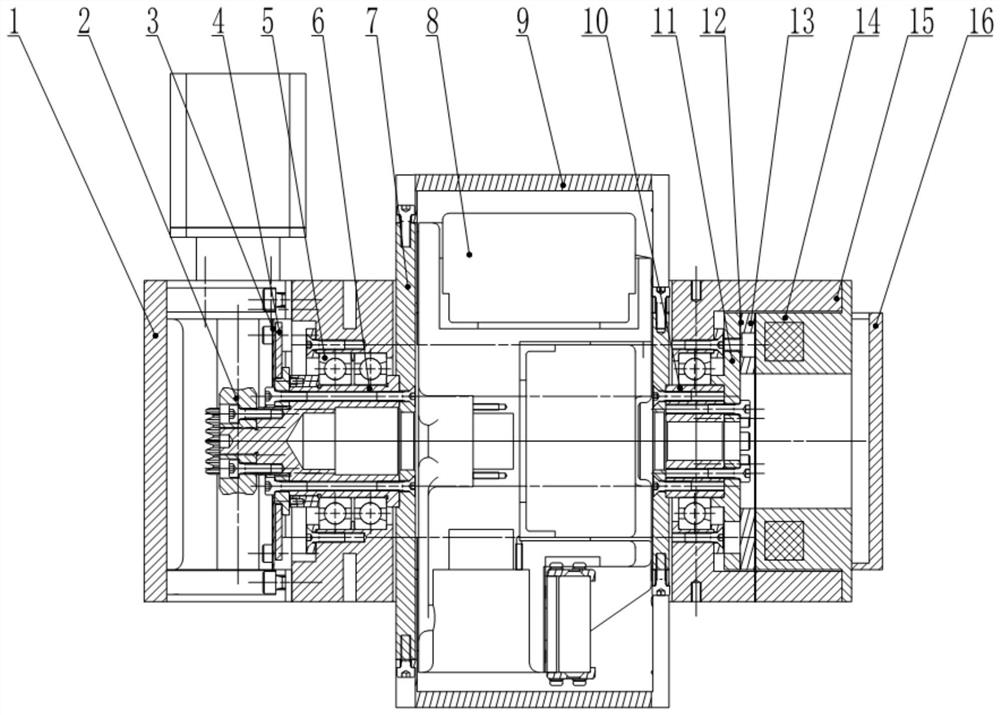
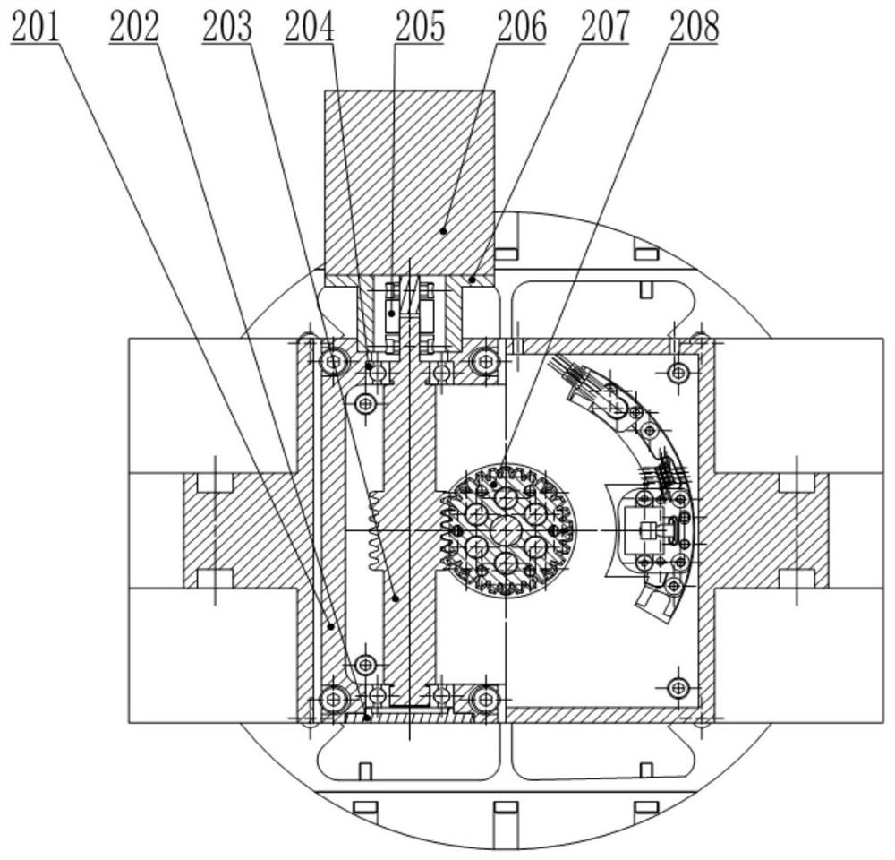
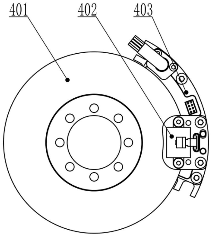
[0049] see Figure 1-Figure 4 According to the present invention, a self-locking navigation inertial group 8 indexing locking mechanism of an electromagnetic brake coordinating mechanism includes:

[0050] Institutional framework15;

[0051]The transmission shaft system that is located in the mechanism frame 15 and rotates relative to the mechanism frame 15, the transmission shaft system at least includes the first transmission locking shaft 6, the hollow shaft 7 and the second transmission locking shaft arranged coaxially in sequence 10;

[0052] The driving self-locking device 2 connected to the end of the first transmission locking shaft 6, through which the driving self-locking device 2 realizes the driving self-locking and the rotational driving of the transmission shaft system;

[0053] An electromagnetic braking device connected to the end of t...


PUM


Abstract

The invention discloses an electromagnetic braking cooperation mechanism self-locking navigation inertial unit transposition locking mechanism, and belongs to the technical field of space navigation control, and aims to solve the problems in the prior art that a mechanism toothed disc is stuck and cannot be tested continuously, the failure rate is high, the mechanism test error is large, the mechanism state cannot be freely switched, and the test efficiency is low. The electromagnetic braking cooperation mechanism self-locking navigation inertial unit transposition locking mechanism comprises: a mechanism frame; a transmission shaft system positioned in the mechanism frame and in running fit relative to the mechanism frame, wherein the transmission shaft system at least comprises a first transmission locking shaft, a hollow shaft and a second transmission locking shaft which are coaxially arranged in sequence; a driving self-locking device connected with the end portion of the first transmission locking shaft, wherein driving self-locking and rotation driving of the transmission shaft system are realized through the driving self-locking device; an electronic braking device connected with the end portion of the second transmission locking shaft and used for braking the transmission shaft system; and a high-precision split testing device used for measuring the angle change of a navigation inertial unit in the hollow shaft.

Description

technical field [0001] The invention belongs to the technical field of space navigation control, and in particular relates to a navigation inertial group indexing and locking mechanism which is self-locked by an electromagnetic brake coordination mechanism. Background technique [0002] From the completion of assembly to the launch of the missile, it must be self-calibrated to ensure that the error of the navigation inertial group test data is smaller and the flight direction is more accurate. The inertial group indexing / locking mechanism is an important part of the navigation inertial group self-calibration system. Its function is to control the navigation inertial group to rotate at a specified angle and lock the specified position according to the calibration requirements. With the wide application of space navigation control technology, the current navigation control system is developing towards higher precision, smaller size and lighter weight. [0003] The inertial gr...

Claims


Application Information

Patent Timeline
Patent Type & Authority Applications(China)
IPC IPC(8): G05G1/10G01C25/00
CPCG05G1/10G01C25/005
Inventor 王循解鹏徐伟谢晓光冯汝鹏徐明林
Owner CHANGCHUN INST OF OPTICS FINE MECHANICS & PHYSICS CHINESE ACAD OF SCI
Why Eureka
Try Eureka