
Static aeroelasticity calculation method for elastic aircraft

A static aeroelasticity, calculation method technology, applied in calculation, computer-aided design, design optimization/simulation, etc., can solve problems such as loss, experimental result influence, sub-transonic wind tunnel Reynolds number inconsistency, etc., to reduce design investment, The effect of shortening the design cycle

Pending Publication Date: 2021-11-30
FUDAN UNIV
View PDF0 Cites 4 Cited by
  • Summary
  • Abstract
  • Description
  • Claims
  • Application Information

AI Technical Summary

Problems solved by technology

Since the middle of the 20th century, researchers have defined aeroelasticity as an independent branch of science and have continued to develop. Although the results of their research have reduced the number of accidents caused by elastic problems, there are still some serious accidents: In the 1960s, the unmanned target drone developed by the Beijing Academy of Aeronautics crashed due to the instability of the airframe caused by aeroelasticity; Hyper-X program hit hard
It is difficult for the usual wind tunnel experiments to fully satisfy the above two conditions. The most common case where the similarity criterion is not satisfied is that the Reynolds number of the sub-transonic wind tunnel does not match.
Taking the Boeing 737 as an example, the aircraft flies at a cruising speed of 927 kilometers per hour at a cruising altitude of more than 9,000 meters, and its Reynolds number reaches Re=2.4×10 7 , while in the 3-meter subsonic wind tunnel experiment, the Reynolds number is only about Re=1.4×10 when the wind speed is 100 meters per second 6 , the difference is large, and the experimental results will be affected

Method used


Image

  • Static aeroelasticity calculation method for elastic aircraft
  • Static aeroelasticity calculation method for elastic aircraft
  • Static aeroelasticity calculation method for elastic aircraft

Examples


Embodiment

[0049] In this embodiment, the derivation process of the method steps is explained in detail in the calculation steps, and some documents and prior art are cited to facilitate understanding.

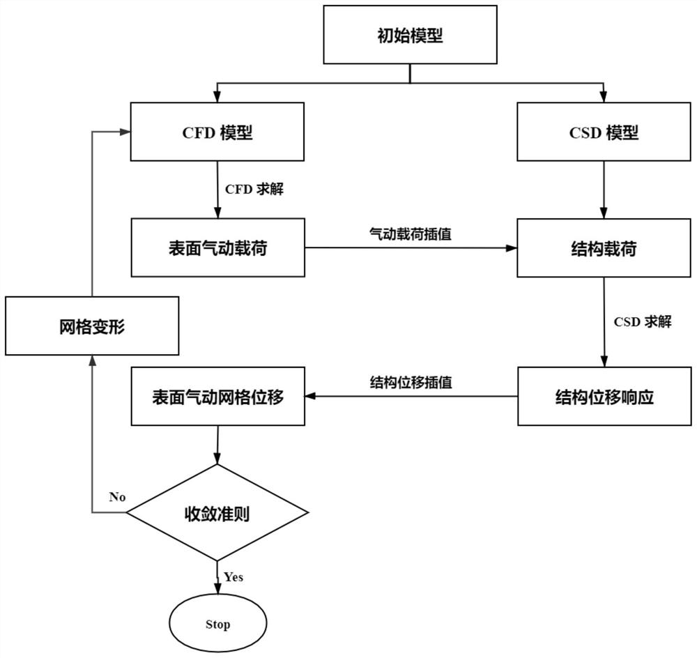
[0050] This embodiment provides a calculation method based on the static aeroelasticity of the aircraft, including: (1) aerodynamic solution method, (2) structural displacement nonlinear solution method, (3) CFD / CSD coupling method; (4) combining the above three The two models are connected into a path to establish a static aeroelastic analysis process

[0051] (1) Aerodynamic solution method

[0052] With the development of CFD methods and computers, CFD calculations are widely used in aircraft design, and the Reynolds-averaged N-S equation is used to solve the flow field.

[0053] Navier-Stokes equation

[0054] The compressible N-S equations in three-dimensional conserved form are as follows:

[0055]

[0056] In the formula, U is a conserved variable.

[0057]

[0058]

...


PUM


Abstract

The invention belongs to the field of aircraft simulation design, and particularly relates to a static aeroelasticity calculation method for an elastic aircraft. According to the method, a CFD method for solving an RANS equation and a finite element method for solving structural nonlinearity are coupled, in the static aeroelasticity claculation process, aerodynamic load and structural displacement need to be transmitted between aerodynamic grids and structural grids, and in order to guarantee precision, an RBF method is adopted for transmitting the aerodynamic load and the structural displacement. On the basis of the RBF method, the aerodynamic / structural interface can be divided into several parts for independent interpolation through the characteristic of accurate interpolation of each interpolation point, the interpolation matrix dimension is reduced, the calculation difficulty is reduced, and the efficiency is improved. A diffusion fairing method is adopted for aerodynamic grid updating, and the method can keep the quality of grids near a wing. According to the calculation method, static aeroelastic deformation is verified by analyzing the CRM wing body assembly model, and a good effect is achieved.

Description

technical field [0001] The invention belongs to the field of aircraft simulation design, and in particular relates to a static aeroelastic calculation method for elastic aircraft. Background technique [0002] When the aircraft actually moves in the air, it will be affected by various factors such as airflow, speed, temperature, and air compressibility. The aerodynamic load loaded on the flexible wing will cause structural deformation of the wing. The aerodynamic properties of the wing are negatively affected. The use of composite materials in the wings of modern large wide-body airliners is very high, and the wings will have a large aeroelastic deformation during flight, which will have a great impact on aerodynamic performance. The problem of aeroelasticity has always been a research hotspot in the field of aviation. Numerical simulation analysis is an experimental method that is non-destructive, can be individually controlled, can be repeated many times, is not limited ...

Claims


Application Information

Patent Timeline
Patent Type & Authority Applications(China)
IPC IPC(8): G06F30/28G06F30/23G06T3/40G06F111/04G06F113/08G06F119/08G06F119/14
CPCG06F30/28G06F30/23G06T3/4007G06F2113/08G06F2119/14G06F2111/04G06F2119/08
Inventor 孙刚张浩裴志刚张毅
Owner FUDAN UNIV
Learn More