
Air source heat pump load optimization method and system

An air source heat pump and load optimization technology, applied in heating methods, space heating and ventilation, heating and ventilation control systems, etc., can solve the lack of cost control, the inability to obtain the configuration quantity of phase change materials at the same time, and no consideration of phase change Material and other issues to achieve the effect of avoiding large-scale fluctuations, low cost, and improving stability

Active Publication Date: 2021-11-30
山东佐耀科技有限公司 +1
View PDF1 Cites 0 Cited by
  • Summary
  • Abstract
  • Description
  • Claims
  • Application Information

AI Technical Summary

Problems solved by technology

[0004] The inventors found that when the existing air source heat pumps are optimally controlled, they either simply perform cost control without considering the impact on indoor temperature fluctuations, or simply perform indoor temperature control without effective cost control; at the same time, the existing The air source heat pump does not take into account the impact of phase change materials in specific applications when optimizing, and it is impossible to obtain the number of configurations of phase change materials at the same time

Method used


Image

  • Air source heat pump load optimization method and system
  • Air source heat pump load optimization method and system
  • Air source heat pump load optimization method and system

Examples


Embodiment 1

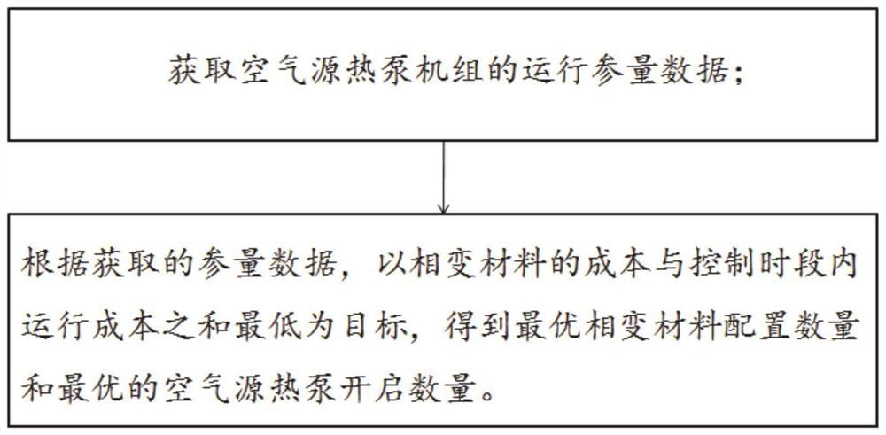
[0031] Such as figure 1 As shown, Embodiment 1 of the present disclosure provides an air source heat pump load optimization method, including the following process:

[0032] Obtain the operating parameter data of the air source heat pump unit;

[0033] According to the acquired parameter data, aiming at the lowest sum of the cost of phase change material and the operating cost in the control period, the optimal configuration quantity of phase change material and the optimal number of air source heat pumps are obtained.

[0034] Specifically, include the following:

[0035] Multiple sets of heat pump units of the same model are generally used in parallel to form a group of heat pump units. Automatic control of the heat pump unit group: When the heat in the room is low, only some of the heat pump units can be controlled and the others can be turned off. When the heat in the room is used more, the hot water pump unit can be fully turned on. The air source heat pump system is ...

Embodiment 2

[0080] Embodiment 2 of the present disclosure provides an air source heat pump load optimization system, including:

[0081] The data acquisition module is configured to: acquire the operating parameter data of the air source heat pump unit;

[0082] The load optimization module is configured to: according to the obtained parameter data, aim at the lowest sum of the cost of the phase change material and the operating cost within the control period, and obtain the optimal configuration quantity of the phase change material and the optimal number of the air source heat pump to be turned on.

[0083] The working method of the system is the same as the air source heat pump load optimization method provided in Embodiment 1, and will not be repeated here.

Embodiment 3

[0085] Embodiment 3 of the present disclosure provides a computer-readable storage medium on which a program is stored, and when the program is executed by a processor, the steps in the air source heat pump load optimization method described in Embodiment 1 of the present disclosure are implemented.


PUM


Abstract

The invention provides an air source heat pump load optimization method and system. The method comprises the following steps: acquiring operation parameter data of an air source heat pump unit; and according to the obtained parameter data, obtaining the optimal phase-change material configuration number and the optimal air source heat pump starting number by taking the minimum sum of the cost of the phase-change materials and the operation cost in the control time period as the target. Balanced optimization control of the building indoor temperature, the operation cost and the number of the phase change materials is achieved, the stability of building indoor temperature control is improved while the lowest cost is guaranteed, and large-range fluctuation of the indoor temperature is effectively avoided.

Description

technical field [0001] The present disclosure relates to the technical field of air source heat pumps, in particular to an air source heat pump load optimization method and system. Background technique [0002] The statements in this section merely provide background information related to the present disclosure and may not necessarily constitute prior art. [0003] Air source heat pump is an energy-saving device that uses high-level energy to make heat flow from low-level heat source air to high-level heat source. Convert it into high-level thermal energy that can be used, so as to achieve the purpose of saving part of high-level energy (such as coal, gas, oil, electric energy, etc.). [0004] The inventors found that when the existing air source heat pumps are optimally controlled, they either simply perform cost control without considering the impact on indoor temperature fluctuations, or simply perform indoor temperature control without effective cost control; at the sa...

Claims


Application Information

Patent Timeline
Patent Type & Authority Applications(China)
IPC IPC(8): G06Q10/04G06Q10/06F25B49/00F24F11/64F24F11/61F24F11/46F24F110/10F24F110/12
CPCG06Q10/04G06Q10/0637F25B49/00F24F11/61F24F11/46F24F11/64F24F2110/10F24F2110/12Y02E60/14
Inventor 王洪伟刘萌高嵩孟凡强王丽
Owner 山东佐耀科技有限公司
Learn More