
Zero- reflection network based on complex impedance matching

A complex impedance and impedance matching technology, which is applied in the direction of impedance network, multi-terminal pair network, electrical components, etc., can solve the problems of inability to achieve full-band output impedance matching, multiple stopband reflection signals, etc., achieve wide applicability, solve multiple impedance With reflected signal, to ensure the effect of impedance matching

Pending Publication Date: 2021-11-30
HUAZHONG UNIV OF SCI & TECH
View PDF0 Cites 0 Cited by
  • Summary
  • Abstract
  • Description
  • Claims
  • Application Information

AI Technical Summary

Problems solved by technology

[0006] In view of the defects of the prior art, the purpose of the present invention is to provide a zero-reflection network based on complex impedance matching, aiming to solve the problem that the existing impedance matching network can only achieve impedance matching within the passband, and cannot achieve the output impedance of the full frequency band matching, resulting in the presence of multiple stopband reflected signals

Method used


Image

  • Zero- reflection network based on complex impedance matching
  • Zero- reflection network based on complex impedance matching
  • Zero- reflection network based on complex impedance matching

Examples


Embodiment Construction

[0033] In order to make the object, technical solution and advantages of the present invention clearer, the present invention will be further described in detail below in conjunction with the accompanying drawings and embodiments. It should be understood that the specific embodiments described here are only used to explain the present invention, not to limit the present invention.

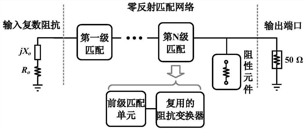
[0034] and figure 1 shown in the conventional active circuit compared to an output matching network for zero reflection, such as figure 2 As shown, based on the same front-stage active circuit, the zero-reflection network can realize complex matching of the output impedance in the whole frequency band, eliminate multiple reflection signals in the stop band, and effectively improve the stability of the active circuit.

[0035] Such as image 3 As shown, the embodiment of the present invention provides a zero-reflection network based on complex impedance matching, including: first-level to Nth-lev...


PUM


Abstract

The invention discloses a zero-reflection network based on complex impedance matching, the input of the zero-reflection network is complex impedance, the output of the zero-reflection network is standard 50 ohm port impedance, and the zero-reflection network comprises N stages of matching circuits which are sequentially connected in series, and a resistive element which is connected with the N stages of matching circuits in parallel; the matching circuit is used for converting input complex impedance into a parallel impedance value of port impedance and a resistive element in a passband, and converting the input complex impedance to tend to infinity in a stop band; and the resistive element is used for further converting infinite impedance generated out of band into a matching state and dissipating the absorbed reflected signal, so that the output port has no reflected signal in a full frequency band; wherein N represents the number of the matching circuits and is a positive integer greater than or equal to 1. According to the invention, a capacitor device of the last stage in the in-band matching network is multiplexed as an impedance converter, a zero reflection network of complex impedance input is realized for the first time, impedance matching conditions are met in a full frequency band, and reflection signals of an output port are eliminated.

Description

technical field [0001] The invention belongs to the technical field of impedance matching, and more specifically relates to a zero-reflection network for complex impedance matching. Background technique [0002] Active circuits are an indispensable and important part of wireless communication link systems, such as radio frequency amplification units, which can realize low-noise amplification or high-power amplification of input signals. However, the traditional active circuit can only match the complex output impedance in the passband, which leads to the re-injection of multiple reflection signals in the stopband into the active circuit when it is cascaded with other devices in the link, deteriorating its stability. Reduce link system performance and other issues. [0003] On the other hand, researchers at home and abroad have proposed a variety of reflection signal absorption circuits for band-pass filters, such as the microstrip zero-reflection filter proposed by Matthew ...

Claims


Application Information

Patent Timeline
IPC IPC(8): H03H7/38
CPCH03H7/38
Inventor 毕晓君曹子兰
Owner HUAZHONG UNIV OF SCI & TECH
Learn More