Oil-containing smoke intercepting equipment

A flue gas and equipment technology, which is applied in the field of oily flue gas interception equipment, can solve the problems of increased equipment running resistance and difficulty in dust removal, and achieves the effect of avoiding frequent replacement and facilitating treatment.

Pending Publication Date: 2021-12-03
重庆华光环境工程设备有限公司
View PDF7 Cites 3 Cited by
  • Summary
  • Abstract
  • Description
  • Claims
  • Application Information

AI Technical Summary

Problems solved by technology

[0003] The present invention intends to provide a kind of oily fume interception equipment to alleviate the problems in the prior art that the exhaust gas enters the dust removal and purification equipment, there are sticky bags, the difficulty of dust cleaning and the increase of equipment running resistance

Method used


Image

  • Oil-containing smoke intercepting equipment
  • Oil-containing smoke intercepting equipment
  • Oil-containing smoke intercepting equipment

Examples


Embodiment 1

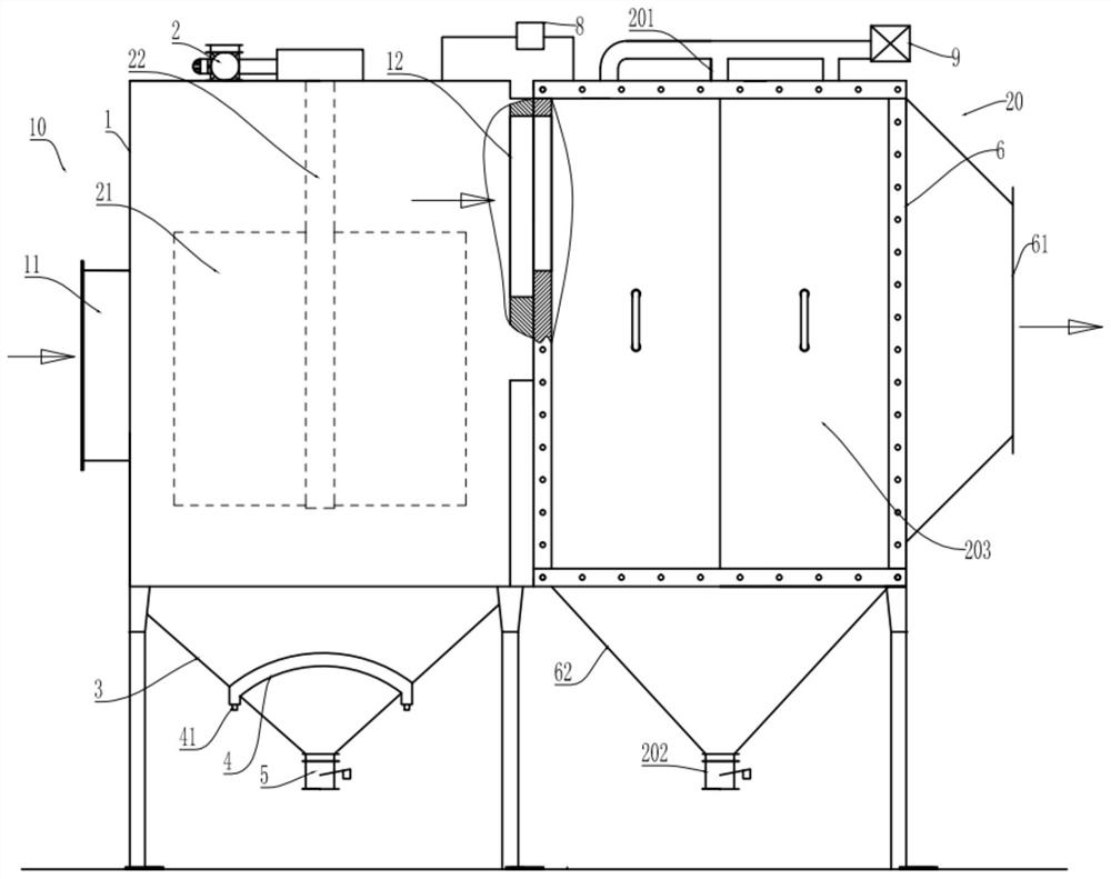
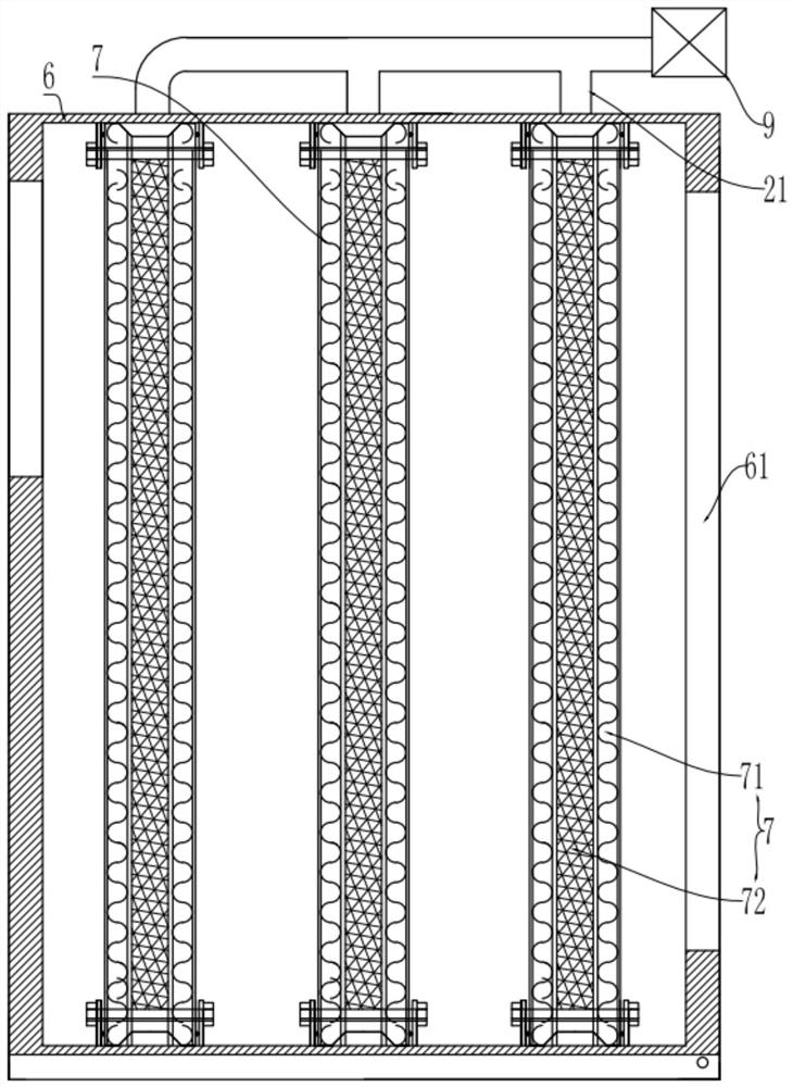
[0035] Embodiment one is basically as attached Figure 1 to Figure 3 As shown, an oily fume interception device is installed at the front end of the bag dust removal and purification equipment, and includes a fume separation unit 10 and an oil filter unit 20. Oil and gas are separated, and the output end of the oil filter unit 20 is connected to the bag dust removal and purification equipment.

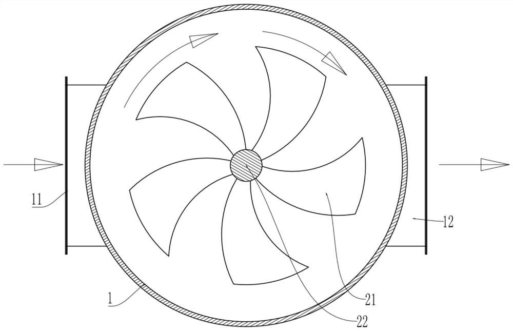
[0036] The oil fume separation unit 10 includes a cylindrical separation chamber 1 and a rotator 2. The separation chamber 1 is formed with an air inlet 11 and an air outlet 12. The bottom of the cylindrical separation chamber 1 is welded with an inverted cone-shaped collection bucket 3. The collection bucket 3 An oil storage tank 4 is processed on the inner side wall of the oil storage tank 4, and an oil outlet 41 is opened on the lowest position of the oil storage tank 4, and the oil outlet 41 communicates with the outside of the separation chamber 1; the oil storage tank 4 extends o...

Embodiment 2

[0050] combine Figure 4 The difference between the second embodiment and the first embodiment is that the shape of the oil storage tank 4 of this embodiment is different, and the oil storage tank 4 of this embodiment is a spiral groove. In addition, the situation that the oil storage tank 4 is a zigzag type or a multi-curve connection type will not be elaborated one by one, but as long as the oil storage tank 4 can extend all the inner walls of the collecting bucket 3, it can be ensured that the collected oil will not flow over the oil storage tank 4 to the The bottom of the collection bucket 3 realizes the separate collection of dust and oil.

Embodiment 3

[0052] combine Figure 5 The difference between the third embodiment and the first embodiment is that the oil storage tank 4 of this embodiment is arranged at the cylindrical bottom of the separation chamber 1, and this embodiment can also realize the separate collection of oil and dust falling into the collection bucket 3.


PUM


Abstract

The invention relates to the technical field of oil-smoke separation, and particularly discloses oil-containing smoke intercepting equipment which comprises an oil-smoke separation unit, the oil-smoke separation unit comprises a separation chamber, the separation chamber comprises an air inlet and an air outlet, the oil-smoke separation unit further comprises a rotator, the output end of the rotator is connected with blades, and the blades are located in the separation chamber; after the rotator drives the blades to rotate, smoke entering from the air inlet can impact the inner wall of the separation chamber and then is discharged from the air outlet; the equipment further comprises an oil filtering unit, the oil filtering unit comprises a filtering plate for intercepting oil mist, the input end of the oil filtering unit is communicated with the air outlet of the separation chamber, and the output end of the oil filtering unit is connected with a cloth bag dust removal and purification equipment. According to the scheme, oil mist in waste gas is separated twice through the oil-smoke separation unit and the oil filtering unit, the oil content in the waste gas is greatly reduced, and the problems that in the prior art, after the waste gas enters cloth bag dust removal and purification equipment, a bag is pasted, dust removal is difficult, and the running resistance of the equipment is increased are solved.

Description

technical field [0001] The invention relates to the technical field of oily fume separation, in particular to an intercepting device for oily fume. Background technique [0002] With the people's emphasis on environmental protection, in some working conditions of production enterprises, it is necessary to capture and purify the industrial dusty waste gas that pollutes the environment through bag dust removal and purification equipment and then discharge it. Among these emissions, in addition to industrial In addition to permanent dust pollutants, a certain proportion of oily waste gas is also mixed. After the dusty and oily waste gas passes through the bag dust removal and purification equipment, there will be some problems. For example, a large amount of oil and dust will adhere to the bag of the dust removal and purification equipment, resulting in There is a problem of difficulty in cleaning the bag and dust, which in turn increases the resistance of the bag dust removal ...

Claims


Application Information

Patent Timeline
Patent Type & Authority Applications(China)
IPC IPC(8): B01D46/10B01D46/00B01D46/44B01D46/48
CPCB01D46/10B01D46/48B01D46/446B01D2258/0283Y02A50/2351
Inventor 陈克煜
Owner 重庆华光环境工程设备有限公司
Why Eureka
Try Eureka