
Device for narrow gap welding and welding method

A welding method and narrow gap technology, applied in the direction of cleaning method using gas flow, welding equipment, auxiliary devices, etc., can solve the problems of reducing welding accuracy, low work efficiency, increasing defective rate, etc., to prevent excessive welding of profiles Large size, convenient positioning and controllable running speed

Active Publication Date: 2021-12-03
山东经典重工集团股份有限公司 +1
View PDF8 Cites 0 Cited by
  • Summary
  • Abstract
  • Description
  • Claims
  • Application Information

AI Technical Summary

Problems solved by technology

[0005] In order to solve the above technical problems, the present invention provides a device and welding method for narrow gap welding, to solve the problem that the existing narrow gap welding device is not equipped with a welding positioning device and an operating device, which greatly reduces the welding accuracy and is not applicable to The welding of long profiles has extremely low work efficiency, and there is no floating welding device and dust removal device. The welding process cannot adjust the welding depth with the change of the outer surface of the profile, resulting in the inability of the shielding gas to achieve the best effect. At the same time, impurities in the groove will cause It affects the overall welding quality, greatly increases the rate of defective products, and is not conducive to cooling. There is no adjustable protection device, which cannot protect the welding joint after welding to prevent burns and stabbing the eyes of the staff. At the same time, it cannot improve the aesthetics of welding and cannot increase The question of economic efficiency

Method used


Image

  • Device for narrow gap welding and welding method
  • Device for narrow gap welding and welding method
  • Device for narrow gap welding and welding method

Examples


Embodiment

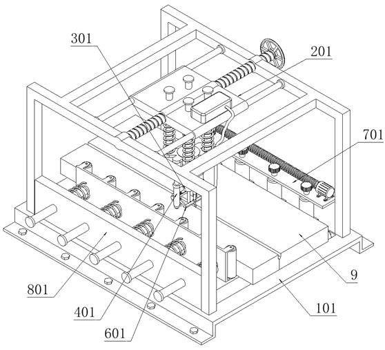
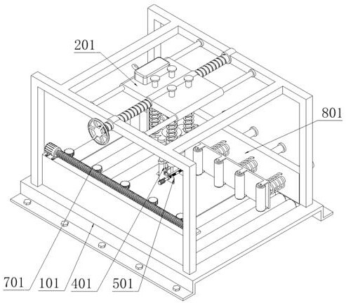
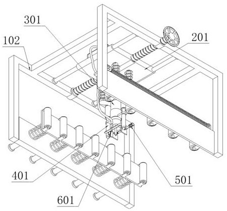
[0080] as attached figure 1 to attach Figure 13 Shown:

[0081] The present invention provides a device for narrow gap welding, comprising a support device 1; a support device 1, which is fixedly connected to the bottom of an operating device 7; a shrinkage joint structure 8 is fixedly connected to the top of the support device 1; the top of the support device 1 The positioning part 2 is fixedly connected; the floating welding part 3 is slidingly connected to the positioning part 2, and the bottom of the floating welding part 3 is slidingly fitted with the adjusting part 4; the adjusting part 4 is fixedly connected with the protection device 5; the front side of the adjusting part 4 A dust removal device 6 is fixedly connected; a welding plate 9 is slidably connected to the supporting device 1 .

[0082] as attached Figure 6 , 12 , 13, the support device 1 includes: the installation base plate 101, the installation base plate 101 is fixedly connected to the bottom of the...


PUM


Abstract

The invention provides a device for narrow gap welding and a welding method. The device comprises a supporting device, wherein the supporting device is fixedly connected to the bottom of an operation device; the top of the supporting device is fixedly connected with a shrinkage joint structure; the top of the supporting device is fixedly connected with a positioning part; the positioning part is slidably connected with a floating welding part, and the bottom of the floating welding part is slidably sleeved with an adjusting part; the adjusting part is fixedly connected with a protection device; the front side of the adjusting part is fixedly connected with a dust removal device; a welding plate is connected to the supporting device in a sliding mode, the floating welding part is connected with floating shafts in a sliding mode, and the floating shafts are sleeved with springs, so that a welding body can be pushed downwards, and automatic adjustment is achieved according to the height of a welded profile; and according to the adjusting part, two distance adjusting shafts at the bottom of a sliding sleeve frame are driven through two electric telescopic rods, the welding depth of the welding body is intelligently controlled, and the welding quality is improved.

Description

technical field [0001] The invention belongs to the technical field of narrow gap welding, and more specifically relates to a device and a welding method for narrow gap welding. Background technique [0002] Narrow gap welding, a kind of pre-welding workpiece in thick plate welding does not open the groove, leaving only a narrow gap of about 10mm, using the gas shielded welding process of multi-layer and multi-pass welding. With the rapid development of industrial technology, narrow gap welding Technology has become the preferred technology for the welding of medium and thick plate structures in modern industrial production, because it involves welding quality issues, a good narrow gap welding device is particularly important at this time. [0003] For example, the application number: CN202010812058.1 relates to an ultra-narrow gap welding device and method for welding pipe fittings, and relates to the field of welding technology. One of them is an ultra-narrow gap welding d...

Claims


Application Information

Patent Timeline
IPC IPC(8): B08B5/02B08B13/00B23K37/00B23K37/02
CPCB08B5/02B08B13/00B23K37/00B23K37/003B23K37/0211B23K37/0408
Inventor 高建国张洪涛郑建康孔德旺王广利郑利昌张万宏
Owner 山东经典重工集团股份有限公司
Learn More