Pressing repair equipment for automobile stamping parts

A technology for automotive stamping parts and equipment, which is applied in the field of pressing repair equipment for automotive stamping parts. It can solve problems such as easy shaking and deviation from position, no dust-proof effect, and insufficient stability, so as to improve the efficiency of pressing repair work and easily push out stamping parts. piece of effect

Inactive Publication Date: 2021-12-03
江西益田机车部件有限公司
View PDF0 Cites 0 Cited by
  • Summary
  • Abstract
  • Description
  • Claims
  • Application Information

AI Technical Summary

Problems solved by technology

[0005] In order to overcome the shortcomings of the traditional press repair equipment for automobile stamping parts, which are not stable enough during the pressing process, easily shake and deviate from the position, and have no dust-proof effect, and dust is easy to stick to the stamping parts, the technical problem of the present invention is: to provide a Pressing and repairing equipment for automobile stamping parts that can clamp stamping parts to increase stability and prevent dust

Method used


Image

  • Pressing repair equipment for automobile stamping parts
  • Pressing repair equipment for automobile stamping parts
  • Pressing repair equipment for automobile stamping parts

Examples


Embodiment 1

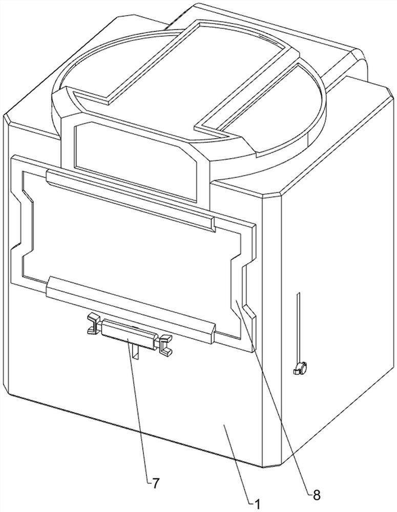
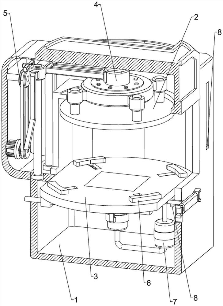
[0035] A kind of pressing repair equipment for automobile stamping parts, such as figure 1 , figure 2 , image 3 , Figure 4 , Figure 5 , Figure 6 , Figure 7 , Figure 8 and Figure 9 As shown, it includes a housing 1, a pressing block 2, a placement table 3, a pressing mechanism 4, a driving mechanism 5, and a clamping mechanism 6. A pressing mechanism 4 is installed on the upper side of the housing 1, and a pressing block is connected to the pressing mechanism 4. 2. A placement platform 3 is fixedly connected to the middle side of the housing 1 , a drive mechanism 5 is connected between the rear side of the housing 1 and the pressing mechanism 4 , and a clamping mechanism 6 is provided between the placement platform 3 and the pressing mechanism 4 .

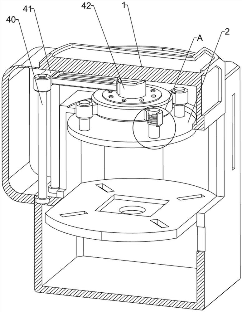
[0036] The pressing mechanism 4 includes a guide rod 40, a first slider 41, a special-shaped block 42 and a first spring 43. The rear side of the housing 1 is welded with a guide rod 40 symmetrically on the left and r...

Embodiment 2

[0041] On the basis of Example 1, such as figure 1 , figure 2 , Figure 10 , Figure 11 , Figure 12 , Figure 13 , Figure 14 and Figure 15 As shown, a lifting assembly 7 is also included, and the lifting assembly 7 includes a handle 70, a piston cylinder 71, a piston rod 72, a fourth spring 73, an air outlet pipe 74 and a top plate 75, and a sliding type is installed in the middle of the front side of the lower part of the housing 1. Pull handle 70, piston cylinder 71 is installed in the front side of the lower part of the housing 1 and the middle of the bottom of the placing table 3, the upper side of the front side piston cylinder 71 is slidably connected to the piston rod 72, and the inner side of the middle piston cylinder 71 is also slidably connected to the piston Rod 72, the front piston rod 72 is connected with the rear side of the pull handle 70, the fourth spring 73 is connected between the piston rod 72 and the piston cylinder 71, the middle fourth spring ...


PUM


Abstract

The invention relates to repair equipment, in particular to pressing repair equipment for automobile stamping parts. According to the pressing repair equipment for the automobile stamping parts, the stamping parts can be clamped, stability is improved, and dust can be prevented. The pressing repair equipment for the automobile stamping parts comprises a shell, a pressing mechanism arranged at the upper side of the interior of the shell, a pressing block arranged on the pressing mechanism, a placement table arranged at the middle side of the interior of the shell, and a driving mechanism arranged between one side of the interior of the shell and the pressing mechanism. A baffle can be opened or closed under the action of vertical movement of a connecting rod, people can place the stamping parts or collect the stamping parts conveniently after the baffle is opened, dust can be prevented from falling on the stamping parts after the baffle is closed, and after a stop lever moves leftwards to stop a front piston rod, the pressing repair work efficiency of the stamping parts is effectively improved.

Description

technical field [0001] The invention relates to a repairing device, in particular to a pressing repairing device for automobile stamping parts. Background technique [0002] With the continuous development of the automobile industry, the demand for automobile stamping parts is also increasing. Automobile stamping parts are indispensable parts in automobiles. The performance of stamping parts can reflect the service life of automobiles. [0003] As we all know, stamping parts are plasticized or repaired under a certain pressure. Nowadays, in the traditional automobile stamping parts pressing and repairing equipment, the stamping parts are not stable enough during the pressing process, and they are prone to shaking and deviation from the position, causing stamping parts The waste of resources will also increase people's work intensity, and there is no dust-proof effect. The stamping parts are always exposed to the air, and the dust is easy to stick to the stamping parts, which...

Claims


Application Information

Patent Timeline
Patent Type & Authority Applications(China)
IPC IPC(8): B21D43/00B21D45/04B21D1/12B21D3/10B21D53/88
CPCB21D43/003B21D45/04B21D1/12B21D3/10B21D53/88
Inventor 戴益林
Owner 江西益田机车部件有限公司
Why Eureka
Try Eureka