Magnetic steel sheet feeding mechanism

A magnetic steel sheet and material storage technology, which is applied in the field of magnetic steel sheet feeding mechanism, can solve problems such as increased production costs, motor quality problems, and magnetic steel sheet fragmentation, so as to improve production efficiency, reduce production costs, and achieve high assembly quality Effect

Active Publication Date: 2021-12-03
GUANGDONG LYRIC ROBOT INTELLIGENT AUTOMATION CO LTD
17 Cites 1 Cited by

AI-Extracted Technical Summary

Problems solved by technology

[0003] In the existing motor assembly process, the magnetic steel sheet needs to be inserted on the rotor. With the continuous improvement of the motor torque output performance requirements, the rotor of the motor is designed with various types and types of magnetic steel sheets to achieve To improve the performance of the motor, different batches of rotors need to be inserted with different types of magnetic steel sheets. However, the existing motor assembly equipment can only load one type and type of magnetic steel sheets, and cannot be compatible with different types of magnetic steel sheets....

Method used

After the clamping assembly 20 grabs the magnetic steel sheet on the feeding assembly 10, the magnetic steel sheet is rotated to below the press-fit assembly, and the press-fit assembly 30 grabs the magnetic steel sheet on the clamp assembly 20 and moves to the press-fit The insertion station of the platform 40, and then insert the magnetic steel sheet into the rotor on the insertion jig 42, for this reason, the accuracy of the position needs to be ensured when the rotating plate 41 of the press-fitting platform 40 rotates, and then the press-fitting components can be guaranteed 30 can accurately insert the magnetic steel sheet into the inserting jig 42, and replace the existing equipment by grabbing and pressing the magnetic steel sheet through the pressing assembly 30 to naturally drop the magnetic steel sheet into the rotor, and grasp it through the pressing assembly 30 Pressing can make the magnetic steel sheets not easy to break and improve the pressing quality of the magnetic steel sheets.
Concrete, as shown in Figure 4, press-fitting platform 40 comprises the rotating plate 41 that rotatably sets, and several inserting jigs 42 that are annularly arranged on rotating plate 41, wherein inserting jigs 42 Including four, four inserting jigs 42 respectively correspond to a loading and unloading station of the rotor, two magnetic steel sheet inserting stations and a detection station, a second detection assembly 43 is set above the detection station, and the rotor is placed On the inserting jig 42, the rotor is moved to two inserting stations sequentially through the rotation of the rotating plate 41, wherein the two inserting stations are correspondingly provided with two sets of feeding assemblies 10 and clamping assemblies 20, wherein two The same size and different types of magnetic steel sheets can be placed in the group feeding assembly 10, and the same size and different types of magnetic steel sheets on the feeding assembly 10 can be grabbed by the clamping assembly 20 to meet the requirements of assembling the same size and different types of magnetic steel sheets on the rotor. Assembly requirements for magnetic steel sheets. It is also possible that magnetic steel sheets of the same type and size can be placed in the two sets of feeding assemblies 10 , and two sets of feeding as...

Abstract

The invention relates to the technical field of motor assembly, in particular to a magnetic steel sheet feeding mechanism. A feeding assembly and a clamping assembly are arranged, the feeding assembly comprises a storage assembly, a loading structure used for containing magnetic steel sheets of different sizes is formed on the storage assembly, and then the magnetic steel sheets of different models and sizes are loaded through the loading structure on the storage assembly; the clamping assembly is arranged on the discharging side of the storage assembly, and the magnetic steel sheets on the storage assembly are clamped through the clamping assembly and turned over for feeding; when rotors of different batches are assembled, the magnetic steel sheets of different models and sizes can be fed and assembled to the rotors of different batches just through the storage assembly, feeding of the magnetic steel sheets of different models is compatible, multiple types of feeding rotary tables and feeding clamps do not need to be configured, the assembling quality is high, the production efficiency is greatly improved, and the production cost is reduced.

Application Domain

Technology Topic

Image

  • Magnetic steel sheet feeding mechanism
  • Magnetic steel sheet feeding mechanism
  • Magnetic steel sheet feeding mechanism

Examples

  • Experimental program(2)

Example Embodiment

[0031] Example 1
[0032] Since different batch of rotors may need to insert different sizes and different types of magnetic steel sheets, while the same batch of rotors need to insert the same size and different types of magnetic steel sheets, and different types of magnetic steel sheets also contain a variety of Size, for this reason, when you need to insert different types, size magnetic steel sheets, you need to configure or replace the above-in-one turntable and upper clamps of different types, size magnetic steel sheets.
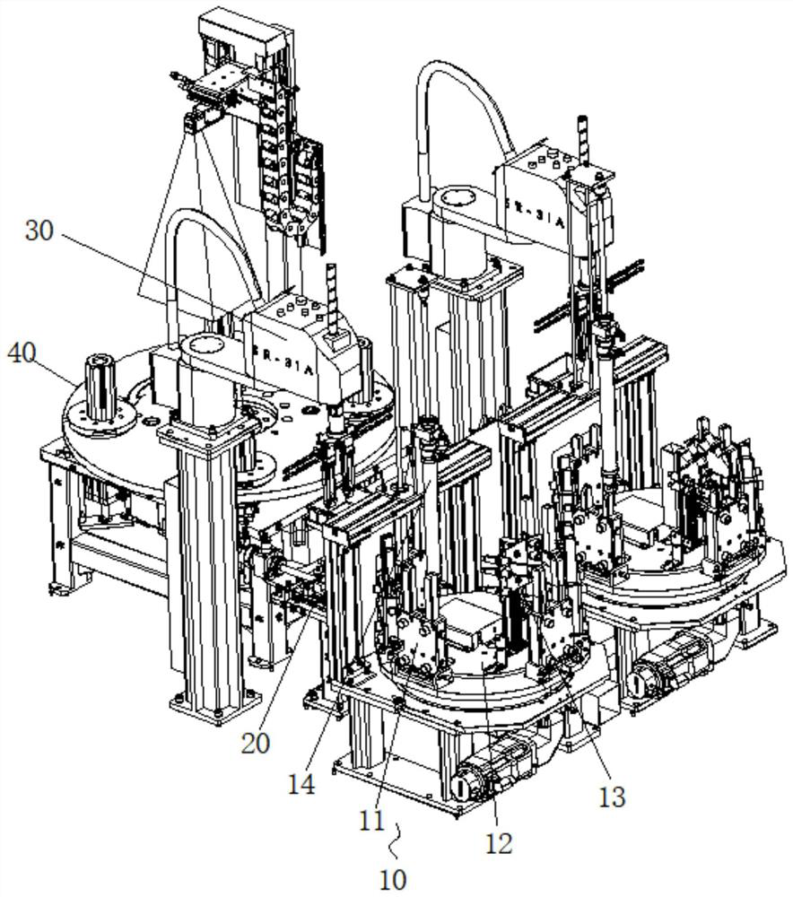
[0033] In order to solve the above technical problems, this embodiment provides a magnetic steel sheet material, such as figure 1As shown, the upper assembly 10 and the clamp assembly 20 are included, and the upper assembly 10 includes at least one set of storage assemblies 11, and the storage assembly 11 is formed to have a loading structure for accommodating different types and size magnetic steel sheets, thereby A magnetic steel sheet having different types of size is realized by the loading structure on the storage assembly 11, and the clamp assembly 20 is disposed at the discharge port 113 of the storage assembly 11, and the magnetic storage assembly 11 is clamped by the clamp assembly 11. Steel sheets are flipped, and only the sheets of different types of magnetic steel sheets can be assembled to the rotors corresponding to different batchs when assembling the rotor to achieve a magnetic steel sheet compatible with different types of magnetic sizes. According to the rotor equipped with different batch, it is not necessary to configure a variety of types of upper turntable and upper fixtures, high assembly efficiency, greatly improve production efficiency and reduce production costs.
[0034] Specifically, such as figure 2 As shown, the upper assembly 10 also includes a turntable 12, and the turntable 12 is driven by the motor 121, and the storage assembly 11 includes several groups, and the plurality of sets of storage assemblies 11 are uniformly distributed on the turntable 12, clamp assembly 20. Located on the side of the turntable 12 and corresponding to one of the storage assemblies 11 and the magnetic steel sheet, the turntable 12 rotates the other set of storage assemblies 11 after the magnetic steel sheet on the set of storage assembly 11 is completed. Corresponding to the clamp assembly 20, a plurality of different types of magnetic steel sheets are stored in a rotor to satisfy the assembly requirements of the same size and different types of magnetic steel sheets in one rotor.
[0035] Further, such as figure 2 As shown, the storage assembly 11 includes a silicon 111 and a tube 112, and a storage tank that can be placed differently size of the tube 112 can be placed in the slider 111, and there is a discharge port in which communication to the storage tank is opened. 113, the tube 112 and the storage tank constitute the loading structure. The number of material tube 112 can be determined according to the actual production requirements, wherein the present embodiment is provided by providing three different sizes 112, three material tube 112 correspond to three different sizes and different types of magnetic steel sheets, three Both the tube 112 can be inserted into the storage tank, and the ball holder 111 is flipped on the turntable 12, and when the insertion tube 112, the bumps 111 to 135 ° can be flipped to insert the tube 112 into the storage tank. Inside, it is convenient for mounting tube 112, which can be fixed to the storage tank through the elastic clamp in the storage tank, and then insert the binder 111 to the inner position, and then insert it. The discharge port 113 communicating into the storage tank is opened at the bottom of the surface of the ball holder 111, and the discharge port 113 is compatible with various magnetic steel sheets, and the clamp assembly 20 is the bottom layer in the tube 112 by extending into the discharge opening 113. The magnetic steel sheet is grabbed, and the magnetic steel sheet is rotated to carry it up.
[0036] In the present embodiment, the storage assembly 11 is provided in the turntable 12 includes a plurality of groups, and both the ball holder 111 of each set of storage assemblies 11, both of the storage tanks, and can be placed on two tube 112, three The material tube 112 of different sizes can be disposed on the ball clip 111 according to the actual production requirements and assembly sequence, and the plurality of groups 111 on the storage assembly 11, and the magnetism 111 on the storage assembly 11 can be formed. The combination of steel sheets is to achieve different assembly needs, greatly improve compatibility and productivity, while reducing no need to configure a variety of types of upper turntable and upper fixtures, reduce production costs.
[0037] Further, in order to facilitate the operation of the procedure, the regular operation is achieved, and the number of magnetic steel sheets is the same, and then, since the size of the magnetic steel sheet is different, the same number of magnetic steel sheets are in the tube 112. The height is inconsistent, for this, when the number of magnetic steel sheets within the detecting material tube 112 is correct, three sets of detection assembly 13 for detecting the inner magnetic steel sheet height of the insulation tube 112 is provided on the turntable 12. The three sets of detection assemblies 13 correspond to three different types of material tube 112, and is irradiated with three different height positions, and the three sets of detecting assemblies 13 are set to achieve which material tube 112 to detect magnetic steel sheet height. Purpose, high compatibility.
[0038] In order to achieve a magnetic steel sheet on the clamping slider 111, such as Figure 2-3 As shown, the clamp assembly 20 includes a jaw assembly 23, a slide plate 22, and a first driving assembly 21 that extends into the discharge port 113, the slide plate 22, and the first driving assembly 21, and the slide plate 22 supported by the mounting, and the slide plate 22 passes through the slide rail. The structure can slide in the horizontal direction on the mounting frame, and the jaw assembly 23 is pivoted on the slide plate 22, and the jaw assembly 23 can be rotated about the pivot point, and the first driving assembly 21 can be a stretchable stretch on the mounting frame. The cylinder is driven through the first driving assembly 21 to drive the slide plate 22 in the mounting frame, and the jaw assembly 23 is turned around the pivot point of the slide plate 22, and when the jaw assembly 23 is clamped to the discharge port of the ball holder 111 After the magnetic steel sheet, the slide plate 22 is driven toward the direction away from the slider 111 toward the direction away from the slider 111, and the jaw assembly 23 is rotated 90 °, and the purpose of the upper magnetic steel sheet is achieved by the pivot structure.
[0039] Further, such as image 3 As shown, the sliding plate 22 is provided with a fixed end 222 that connects the first driving assembly 21, and the other end of the slide plate 22 is provided with a connecting seat 221, and the jaw assembly 23 is equipped with a connecting plate 231 pivoted to the connecting seat 221. The intermediate of the plate 231 is pivotally connected to the connecting seat 221, and there is a guide structure (not shown) in the end portion of the connecting plate 231, and in the middle of the slide plate 22 pull the middle portion of the connecting plate 231, the connecting plate 231 other end of the jaw Component 23 is rotationally up. Further, the opening of the jaw assembly 23 is rotated 90 ° through the first driving assembly 21 to drive the slide plate 22 toward the away from the blanking clip 111, and the sliding plate 22 is provided with a finite column 223, and the jaw assembly 23 is rotated 90 °. The limit column 223 achieves a limit, ensuring the accuracy of subsequent magnetic steel sheets.
[0040] The jaw assembly 23 extends into the discharge port 113 of the magazine 111 grabs the bottom of the magnetic steel sheet, in order to ensure that each time it can capture the magnetic steel sheet, such as figure 2 As shown, the storage assembly 11 also includes a lower pressing assembly 14 suspended from the tube 112, and the lower pressing assembly 14 includes a rod 141 and a driving pressure rod 141 extending into the tube 112, the bottom of the pressure rod 141. Magnetic steel sheets acting within the tube 112 achieve a magnetic steel sheet to ensure the bottom layer.
[0041] In order to achieve the magnetic steel sheet of the storage assembly 11 to the rotor, if figure 1 , Figure 4 As shown, the present embodiment also includes a press-fitting platform 40 for loading the rotor and a press assembly 30 suspended on the clamp assembly 20, and the press assembly 30 grabs the magnetic steel sheet on the clamp assembly 20 and inserted. In the rotor of the pressing platform 40, the magnetic steel sheet on the storage assembly 11 is sequentially in order to insert the corresponding position of the rotor.
[0042] Specifically, such as Figure 4 As shown, the pressing platform 40 includes a rotatable rotation plate 41, and a plurality of insert fixture 42 disposed on the rotation plate 41, wherein the cartridge fixture 42 includes four, four inserts. The 42 respectively corresponds to a top and lower material of the rotor, two magnetic steel sheets, and a detection station, which set the second detecting component 43 over the detection station, and the rotor is placed on the plug fixture 42, passed The transfer plate 41 rotates sequentially moves the rotor to the two plug-in stations, wherein the two plug-in stations correspond to two sets of sheet assembly 10 and the clamp assembly 20, wherein the two sets of sheet assembly 10 can be placed the same. Different types of magnetic steel sheets, by gripping the same size different types of magnetic steel sheets on the upper assembly 10 by the clamp assembly 20 to satisfy the assembly requirements of magnetic steel sheets different types of magnetic steel sheets as those in the rotor. It is also possible that the two sets of sheet assembly 10 can place the same type and the same size magnetic steel sheet, and the two sets of sheet assembly 10 and the clamp assembly 20 are provided to achieve efficient assembly. Among them, the magnetic steel sheet inserted on the rotor is detected by the second detecting assembly 43, and the magnetic steel sheet is detected by visually detecting whether there is a defect, and the case where there is a vacancy on the rotor. The steel sheet is inserted accurately and ensures the quality of the rotor assembly.
[0043] The clamp assembly 20 screws the magnetic steel sheet to the press-fitting assembly, and the pressing assembly 30 can capture the magnetic steel sheet on the clamp assembly 20 and move to the pressing platform 40. The insertion station, thereby inserting the magnetic steel sheet into the rotor on the insertion fixture 42, for this, when the rotation plate 41 of the pressing platform 40 needs to ensure the accuracy of the position, in order to ensure that the press assembly 30 can be accurate Insert the magnetic steel sheet into the insertion fixture 42, replacing the existing equipment in the manner of gripping the printer by pressing the compressing assembly 30, replacing the magnetic steel sheet naturally into the rotor, and passes the pressing of the press assembly 30. The magnetic steel sheet is not easily broken, and the mass of magnetic steel sheet is compressed.
[0044] In order to achieve the position accuracy of the insertion fixture 42 when the transfer plate 41 is rotated, the positioning structure 44 for positioning the insertion fixture 42 is provided below the transfer plate 41, and the bottom surface of the plug fixture 42 is provided with a positioning slot. The positioning structure 44 is disposed below the transfer plate 41 and corresponds to the insertion fixture 42, respectively, and the positioning structure 44 includes a positioning groove inserted into the bottom surface of the insertion tool 42 inserted into the pocket fixture 42, respectively. Further, after the transfer plate 41 is rotated in place, the positioning column is further positioned, and the accuracy of the position of the insertion fixture 42 is ensured, and the magnetic steel sheet is accurately inserted on the rotor of the plug fixture 42. . At the same time, the end of the positioning column is tapered, and when the positional deviation is present, when the positioning column is not aligned with the positioning groove, the positioning slot is inserted into the positioning slot through the end of the positioning column, and realizes the correction of the positioning column. Function.

Example Embodiment

[0045] Example 2
[0046] This embodiment provides a magnetic steel sheet material, such as Figure 5 As shown, it is also included that the upper assembly 10, the clamp assembly 20, the press assembly assembly 30, and the pressing platform 40, the upper assembly 10 includes at least one set of storage assembly 11, which is used for accommodation different in the storage assembly 11. The loading structure of the size magnetic steel sheet is further enabled by the loading structure on the storage assembly 11, and the clamp assembly 20 is disposed on one side of the storage assembly 11, and the clamp assembly 20 is passed. The magnetic steel sheet on the storage assembly 11 is flipped, and only the material of the magnetic steel sheet of different models can be assembled to different batch of rotors when assembling the rotor, and is compatible with different models. Magnetic steel sheets, do not need to be configured to configure multiple types of upper turbines and upper fixtures, high assembly efficiency, greatly increase production efficiency and reduce production.
[0047] Wherein, the upper assembly 10 includes a turntable 12, which is different from the first embodiment, such as Figure 5 As shown, the storage assembly 11 includes a limiting block 101 disposed on the turntable 12, and a plurality of active slips 102, the limit block 101, and the limit ball holder 102, which are disposed in the restricted block 101. Structure, there is a plurality of limit ball holders 102 to enclose a tank for loading magnetic steel sheets, by opening a groove on the turntable 12, the limit ball holder 102 is adjusted in the tank by bolt, and then achieves more The distance between the limited position ball holders 102, thereby adjusting the size of the accommodating groove, and realizes the magnetic steel sheets that place different sizes.
[0048] Further, such as Image 6As shown, the clamp assembly 20 includes a conveying material 202, and a push assembly 203, respectively, respectively, respectively, and a grip assembly 201 of the output terminal, and the conveying material 202 is linear vibration, and magnetic steel sheets are realized by vibration. Conveying to the grab assembly 201, the push assembly 203 is used to push the uppermost magnetic steel sheet on the uppermost layer of the restricted ball clip 102 to the conveying material 202, and the push assembly 203 can be a cylinder and a push rod structure, and the assembly 201 is used. The magnetic steel sheet of the conveying material 202 is grasped and the upper material is flipped, and then the magnetic steel sheet on the clamp assembly 20 is grasped by the press assembly 30 and move to the pressing platform 40 for insertion. Wherein, the turntable 12 slides on the table, the bottom is provided with the adjustment knob 106, and the position of the turntable 126 is adjusted by the adjustment knob 106, the relative position between the adjustment of the push assembly 203 and the storage assembly 11 is achieved, ensuring the clamping assembly 20. The push assembly 203 accurately push the magnetic steel sheet to the conveying material 202 for delivery. At the same time, the pirate assembly 203 and the turntable 12 are disposed on the table, and the table is disposed on the bottom plate through the slide structure 103, and the relative position of the push assembly 203 and the conveying material 202, further ensuring the push assembly 203 to block the magnetic steel sheet. Push to the conveying material 202.
[0049] The top rising assembly is also provided at the bottom of the turntable 12, such as Figure 8 As shown, the top riser assembly includes a stem 105 extending to the bottom of the accommodating groove, and a second driving assembly 104 that drives the top rod 105, the second drive assembly 104 is a telescopic cylinder, and the push assembly 203 will limit After the topmost magnetic steel sheet on the bullet holder 102 is pushed to the conveying material 202, the magnetic steel sheet in the limit slider 102 is riser through the top rod 102, and the push assembly 203 pushes the next magnetic steel sheet to Conveying material 202. When the magnetic steel sheet of one of the storage assemblies 11 is completed, the next set of storage assembly 11 is transferred to the clamp assembly 20 by rotating by the turntable 12, and the clamping assembly 20 and the top rising assembly are mounted to the next reside. The magnetic steel sheet of the material assembly 11 is placed.
[0050] Further, such as Figure 7 Distance Figure 7 for Image 6 A portion of the A portion enlarges, and the grab assembly 201 includes a rotary cylinder 2011 and a block 2012, an end surface of the socket 2012, forming a magnetically embedded opening, magnetic steel sheet moving and extending the end of the conveying material 202 Further, the magnetic steel sheet protruded from the end portion of the conveying cartridge 202 inserted into the opening of the insertion block 2012 by rotating the cylinder 2011, and then rotates the magnetic steel sheet to the press assembly by rotating the cylinder 2011. 30 below, in turn, through the press assembly 30, transfer the magnetic steel sheet on the socket 2012 to the pressing platform 40 for insertion. Among them, an alignment sensor 2013 is provided at the end portion of the conveying material 202, and the through hole 2014 is opened through the laser light of the diamond sensor 2013 in the side surface of the socket 2012, and when the magnetic steel sheet is embedded in the socket 2012, The loosening sensor 2013 senses a magnetist, indicating that the magnetic steel sheet has been embedded, and the rotary cylinder 2011 is rotated so that the magnetic steel sheet is flipped to the compression assembly 30, and the displacement sensor 31 is disposed on the press assembly 30, the press assembly 30 When the magnetic steel sheet is inserted on the rotor, by the displacement sensor 31 detects the lower pressure displacement of the pressing assembly 30 in real time, it is accurately controlled to control the pressure-loaded position to ensure that the magnetic steel sheet is pressed in place and does not cause magnetic Steel sheet is damaged.
[0051] In summary, in one or more embodiments of the present application, the present application includes a tape assembly including a storage assembly, and is formed to accommodate different sizes of magnetic steel sheets in the storage assembly. The loading structure, which enables magnetic steel sheets loaded with different model sizes by the loading structure on the storage assembly, and the clamp assembly is disposed on the surface of the storage assembly, and the magnetic steel sheets on the storage assembly are passed through the clamp assembly. And flip the feed, only the material of the magnetic steel sheet of different types of magnetic steel sheets can be assembled to different batch rotors when assembling different batch rotors, and the magnetic steel sheets compatible with different models can be achieved. No need to configure a variety of types of charged turndomers and feed fixtures, high assembly quality, greatly improve production efficiency and reduce production costs.

PUM

no PUM

Description & Claims & Application Information

We can also present the details of the Description, Claims and Application information to help users get a comprehensive understanding of the technical details of the patent, such as background art, summary of invention, brief description of drawings, description of embodiments, and other original content. On the other hand, users can also determine the specific scope of protection of the technology through the list of claims; as well as understand the changes in the life cycle of the technology with the presentation of the patent timeline. Login to view more.

Similar technology patents

Glass tube clamp

Owner:KUNSHAN FOR EASIER AUTOMATION TECH

Copper pipe clamp

Owner:KUNSHAN FOR EASIER AUTOMATION TECH

Classification and recommendation of technical efficacy words

  • Increase productivity
  • Improve assembly quality

Method and system to define implement and enforce workflow of a mobile workforce

ActiveUS20130090969A1Improves work force capabilityIncrease productivityResourcesWorkflow processWorkflow
Owner:HYPHEN SOLUTIONS LLC

Apparati, methods, and compositions for universal microbial diagnosis, detection, quantification, and specimen-targeted therapy

InactiveUS20120129794A1Increase productivityAccurate and rapid and sensitive microbial diagnosis and detection and quantificationAntibacterial agentsBiocidePopulationMolecular Targeted Therapies
Owner:DOWD SCOT E +2

General method for laying out and assembling wedge-shaped duct pieces

InactiveCN103758531ASimplify the manufacturing and assembly processImprove assembly qualityUnderground chambersTunnel liningEngineeringShield tunneling
Owner:中海建筑有限公司
Why Eureka
Try Eureka