Cutter installing and lifting device for circular cutter die-cutting machine

A hoisting device and a round knife mold technology, which is applied in hoisting devices, cranes, transportation and packaging, etc., can solve problems such as limited working space, inability to accurately align the cutter shaft, and inconvenient adjustment of positions in multiple directions.

Pending Publication Date: 2021-12-03
廊坊纽特科技有限公司
View PDF0 Cites 0 Cited by
  • Summary
  • Abstract
  • Description
  • Claims
  • Application Information

AI Technical Summary

Problems solved by technology

[0002] With the wide application of die-cutting machines, the application range of die-cutting machines has been increasing and expanding, and some particularly large cutter shafts (over 120 kg) have appeared, and the working space is limited. This kind of cutter shaft cannot be installed by one person. Disassembly, so there is a great safety hazard in the installation process
[0003] Therefore, it is necessary to use a hoisting device to lift and install the cutter shaft, but the existing device is not conducive to the alignment installation with the frame, which is easy to cause interference, and it is inconvenient to adjust the position in multiple directions after lifting, resulting in the inaccurate alignment of the cutter shaft. The use stability is poor and needs to be improved

Method used


Image

  • Cutter installing and lifting device for circular cutter die-cutting machine
  • Cutter installing and lifting device for circular cutter die-cutting machine
  • Cutter installing and lifting device for circular cutter die-cutting machine

Examples


Embodiment Construction

[0029] The following will clearly and completely describe the technical solutions in the embodiments of the present invention in conjunction with the accompanying drawings in the embodiments of the present invention; obviously, the described embodiments are only part of the embodiments of the present invention, not all embodiments, based on The embodiments of the present invention and all other embodiments obtained by persons of ordinary skill in the art without making creative efforts belong to the protection scope of the present invention.

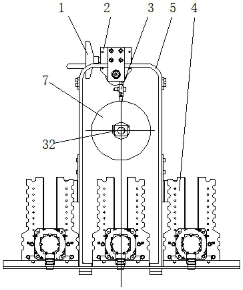
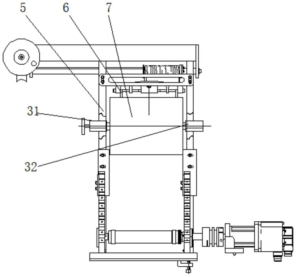
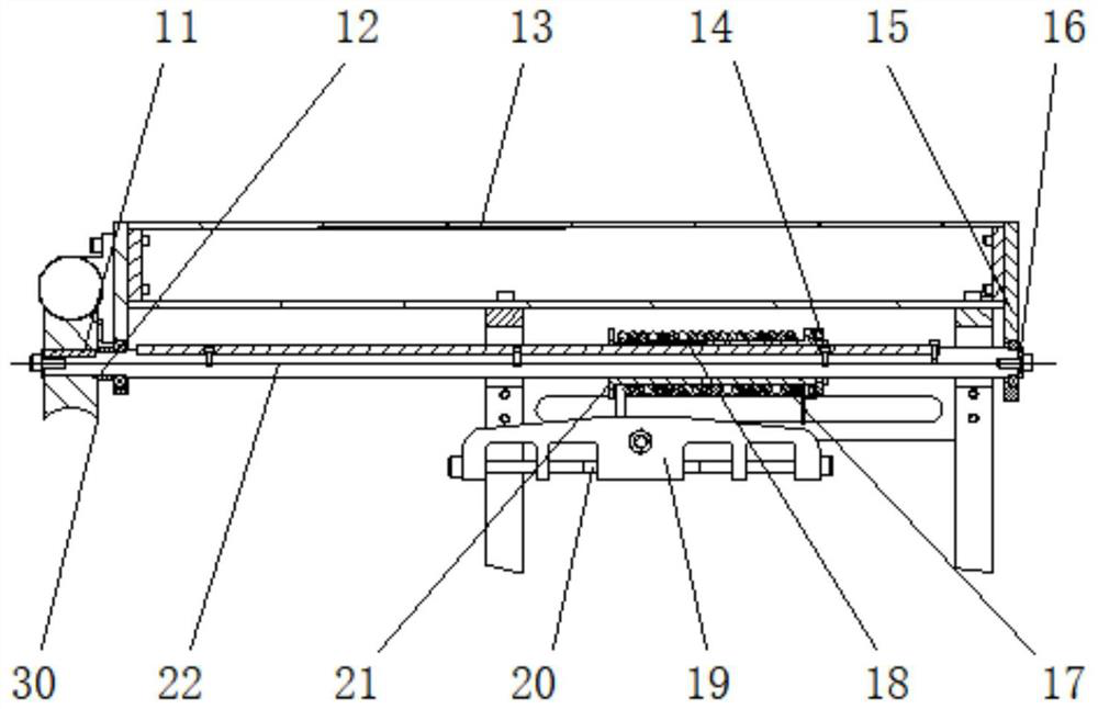
[0030] see Figure 1-5 , a knife-loading device for a round knife die-cutting machine, including frame 4, please refer to figure 1 , image 3 ,and Figure 5 , the side of the frame 4 is fixed with a U-shaped bracket 5, which can be installed in the upper position of the frame 4 in alignment, and at the same time will not interfere with the rotation of the bottom parts, which is convenient for installation and positioning, and is benefi...


PUM


Abstract

The invention discloses a cutter installing and lifting device for a circular cutter die-cutting machine. The cutter installing and lifting device comprises a rack, a U-shaped support is fixedly mounted on the side face of the rack, a mounting plate is slidably mounted at one end of the U-shaped support, a transmission shaft is rotatably mounted on the surface of one side of the mounting plate, and a long flat key is fixedly mounted on the surface of the transmission shaft; a winding sleeve is slidably mounted on the surface of the long flat key, a steel wire rope is fixedly wound on the surface of the winding sleeve, a steel wire gland is fixedly connected to the other end of the winding sleeve, a lifting frame is fixedly connected to the other end of the steel wire rope through a steel wire rope chuck, and a transverse bolt is fixedly connected to the surface of the other side of the lifting frame, a lifting ring is slidably mounted on the surface of the transverse bolt, and a cutter shaft is fixedly mounted on the other end of the lifting ring. According to the cutter installing and lifting device for the circular cutter die-cutting machine, the labor intensity is reduced, the working efficiency is improved, the labor cost is reduced, the safety of operators is ensured, and damage to the cutter shaft and equipment during mounting and dismounting of a large-scale cutter shaft can be effectively avoided.

Description

technical field [0001] The invention relates to the field of die-cutting equipment, and more specifically relates to a knife-loading and hoisting device for a round-knife die-cutting machine. Background technique [0002] With the wide application of die-cutting machines, the application range of die-cutting machines has been increasing and expanding, and some particularly large cutter shafts (over 120 kg) have appeared, and the working space is limited. This kind of cutter shaft cannot be installed by one person at all. Therefore, there is a great potential safety hazard during the installation process. [0003] Therefore, it is necessary to use a hoisting device to lift and install the cutter shaft, but the existing device is not conducive to the alignment installation with the frame, which is easy to cause interference, and it is inconvenient to adjust the position in multiple directions after lifting, resulting in the inability of accurate alignment of the cutter shaft. ...

Claims


Application Information

Patent Timeline
Patent Type & Authority Applications(China)
IPC IPC(8): B66C19/02B66C11/16B66D1/14B25B27/00
CPCB66C19/02B66C11/16B66D1/14B25B27/00
Inventor 李思成
Owner 廊坊纽特科技有限公司
Why Eureka
Try Eureka