Connecting structure and sensor thereof

A connection structure and sensor technology, applied in the field of sensors, can solve the problems of difficult positioning and alignment, high operator requirements, waste of bonding materials, etc., to improve yield and operation efficiency, simple and effective connection operation, and save manufacturing costs. Effect

Pending Publication Date: 2020-11-17
东莞市百赛仪器有限公司
View PDF0 Cites 0 Cited by
  • Summary
  • Abstract
  • Description
  • Claims
  • Application Information

AI Technical Summary

Problems solved by technology

[0006] Problems in the prior art: 1. It is difficult to locate and align the ring gasket when it is bonded to the elastomer, which is time-consuming and easily leads to defective products; 2. It is difficult to locate and align the circuit board when it is bonded to the ring gasket. Time-consuming and easy to lead to defective products; 3. When the ring gasket is bonded to the elastomer, and / or the circuit board is bonded to the ring gasket, it is easy to cause the coated bonding material to overflow, which must be cleaned, and it is easy to remove Bringing it to other parts will cause pollution, and it will easily cause the displacement of the gasket and the circuit board when it is removed at the same time. It needs to be repositioned and aligned, which is time-consuming and likely to lead to defective products; 4. The ring gasket and the elastomer are bonded to a plane contact And the area is limited, which often leads to insufficient bonding strength and difficult control, high requirements for operators, low work efficiency, and waste of bonding materials; 5. The ring gasket is bonded to the elastomer, and the circuit board is bonded to the ring The gasket requires two independent coatings of bonding materials, which complicates the process and lengthens the working hours

Method used


Image

  • Connecting structure and sensor thereof
  • Connecting structure and sensor thereof
  • Connecting structure and sensor thereof

Examples


Embodiment Construction

[0038] The concrete implementation of the present invention is described in detail below, it is necessary to point out here that the following implementation is only used for further description of the present invention, and can not be interpreted as limiting the protection scope of the present invention. Some non-essential improvements and adjustments still belong to the protection scope of the present invention.

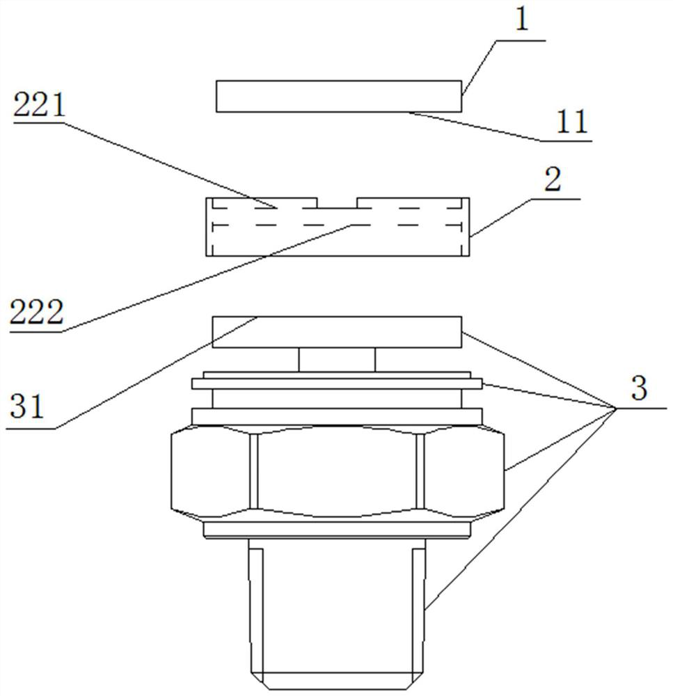
[0039] refer to Figure 1 to Figure 5 , a connection structure comprising: a first unit (1), a second unit (2) and a third unit (3), the first unit (1) is connected to the second unit (2), the second unit The second unit (2) is connected with the third unit (3), the second unit (2) is located in the middle of the first unit (1) and the third unit (3), and connects the first unit (1) and the third unit (3). The role of unit (3).

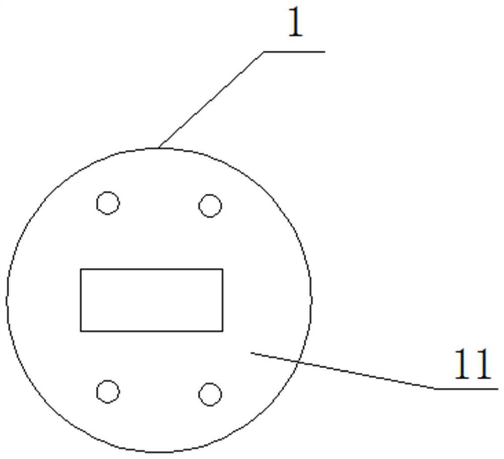
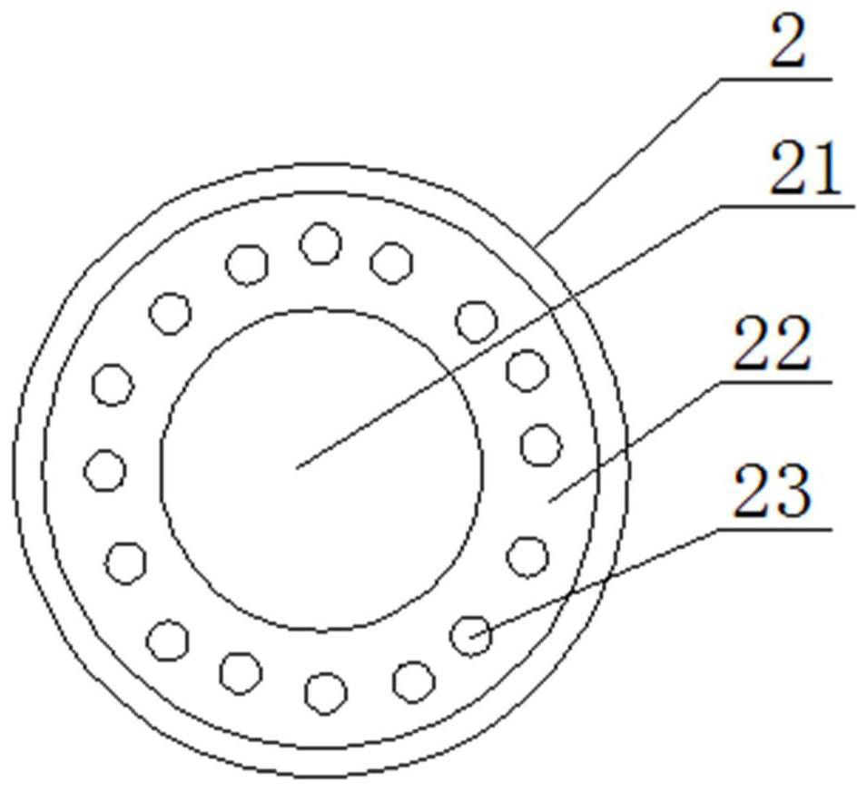
[0040]Specifically, the first unit (1) includes a first unit connecting portion (11); the second unit (2) includes a hollow portion (21...


PUM


Abstract

The invention discloses a connecting structure and a sensor thereof, and relates to the technical field of sensors. The connecting structure comprises a first unit, a second unit and a third unit, anupper boss structure of the second unit is connected with the first unit in a clamped and matched mode, a lower boss structure of the second unit is connected with the third unit in a clamped and matched mode, and a connecting part of the second unit is provided with a hollowed-out structure. The invention further discloses an assembling method of the connecting structure. The connection operationamong the first unit, the second unit and the third unit is simple and effective, the problems of inaccurate alignment among the three units and/or excessive bonding materials are avoided, the yieldand the operation efficiency are improved, the usage amount of the bonding materials is reduced, and the cost is saved.

Description

technical field [0001] The invention relates to the technical field of sensors, in particular to a connection structure and a sensor thereof. Background technique [0002] A sensor is a device or device that can sense what is being measured and convert it into a usable output signal according to certain rules, usually consisting of sensitive elements and conversion components. Among them, the sensitive element refers to the part of the sensor that can directly sense or respond to the measured; the conversion component refers to the part of the sensor that converts the measured change sensed or responded by the sensitive element into a signal suitable for transmission or measurement. [0003] Generally, according to the physical quantity measured by the sensor, it can be divided into displacement sensor, pressure sensor, acceleration sensor, temperature sensor and so on. The commonly referred to as a pressure sensor refers to a device or device that can sense fluid pressure ...

Claims


Application Information

Patent Timeline
Patent Type & Authority Applications(China)
IPC IPC(8): H05K1/18H05K3/30G01D11/00G01D21/00
CPCG01D11/00G01D21/00H05K1/181H05K3/305
Inventor 欧阳德利
Owner 东莞市百赛仪器有限公司
Why Eureka
Try Eureka