
Large-section wide-span rigid frame bridge swivel beam construction monitoring method and monitoring device

A technology for monitoring devices and large segments, which is applied in the direction of measuring devices, bridges, bridge construction, etc., to achieve the effects of improving position correction efficiency, increasing intelligence, and improving accuracy

Active Publication Date: 2021-12-03
CHINA RAILWAY SEVENTH GRP CO LTD +1
View PDF6 Cites 0 Cited by
  • Summary
  • Abstract
  • Description
  • Claims
  • Application Information

AI Technical Summary

Problems solved by technology

[0004] The object of the present invention is to provide a construction monitoring method and a monitoring device for a large-segment wide-span rigid-frame bridge swivel girder, so as to solve the related problems raised in the above-mentioned background technology

Method used


Image

  • Large-section wide-span rigid frame bridge swivel beam construction monitoring method and monitoring device
  • Large-section wide-span rigid frame bridge swivel beam construction monitoring method and monitoring device
  • Large-section wide-span rigid frame bridge swivel beam construction monitoring method and monitoring device

Examples


Embodiment 1

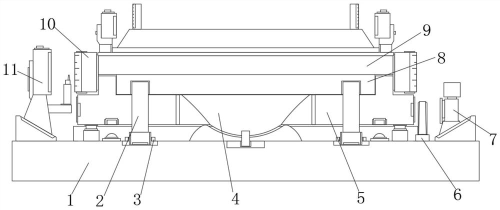
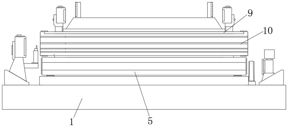
[0040] Example 1, such as Figure 1-2 As shown, through the observation cooperation of three sets of elevation observation points installed on the cantilever on the upper part of the swivel body, four sets of tower rulers and two leveling instruments, the whole process of swivel body can be monitored. The center line of the total station is used to correct the body position, and the deviation of the center line is allowed to be no more than 2cm, which is convenient for the measurement personnel to report the data obtained to the measurement and control personnel in time until the deviation requirements are met.

Embodiment 2

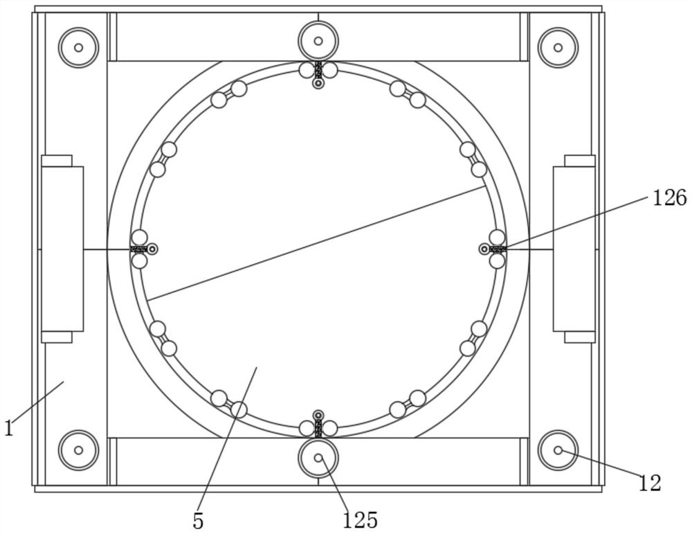
[0041] Example 2, such as Figure 1-5 As shown, utilizing the mutual cooperation of the second total station 11 and the swivel scale mark 10, the axis rotation angle of the swivel and the height measurement and the distance of the rotation can be monitored respectively, so that it is convenient to pass the second total station 11 and the swivel body. The scale mark 10 can control the tracking and monitoring of the rotation smoothly, and improve the monitoring efficiency and correction processing of the abnormal change of the rotation.

[0042] Working principle: When the monitoring device is in use, as the upper bearing platform 5 rotates on the lower axis with the cooperation of the ball hinge 4, the upper bearing platform 5 drives multiple sets of legs 2 to rotate under the guidance of the slideway bracket 3, and at this time The 360° prism 6 can be used to correspond to the structure of the first total station 7, and the plane observation and elevation observation can be ca...


PUM


Abstract

The invention discloses a large-section wide-span rigid frame bridge swivel beam construction monitoring method and a monitoring device, the monitoring device comprises a lower bearing platform, a spherical hinge is arranged at the middle position of the top of the lower bearing platform, an upper bearing platform, an upper turntable and an upper rotating disc which are mutually stacked and assembled are respectively arranged at the top of the spherical hinge, and supporting legs are uniformly arranged on the outer side of the bottom of the upper turntable. The outer side, close to the spherical hinge, of the top of the lower bearing platform is provided with a slide way support matched with the supporting legs, and the middle position of one side of the top of the lower bearing platform is provided with a prism and a first total station; according to the invention, through the mutual cooperation of the prism, the first total station, a swivel scale mark and a second total station, the real-time monitoring and elevation observation of the axis operation amplitude of the swivel system are facilitated, so that the rotation angle and axis deviation of the swivel and the numerical value and control of the swivel speed are more accurate and stable; therefore, the swivel is controlled by the monitoring system to stably rotate along the axis.

Description

technical field [0001] The invention relates to the technical field of bridge swivels, in particular to a construction monitoring method and a monitoring device for a swivel girder of a large-segment wide-span rigid frame bridge. Background technique [0002] Bridge swivel construction refers to a construction method in which the bridge structure is prefabricated at a position other than the design axis, and then put in place by swivel. It can convert the work above the obstacle into the operation on the shore or near the ground. According to the bridge structure According to the direction of rotation, it can be divided into vertical rotation construction method, horizontal rotation construction method and the method of combining horizontal rotation and vertical rotation. [0003] During the current bridge swivel construction, a system dedicated to monitoring the bridge swivel mechanism is often required to calculate the actual value and deviation of the swivel body and subs...

Claims


Application Information

Patent Timeline
IPC IPC(8): E01D21/08G01C5/00G01C15/00G01G19/00
CPCE01D21/08G01C5/00G01C15/00G01G19/00
Inventor 毛国利向凯冷有良刘伟高兵杨维晏红曹可可郭朝张剑峰宋志云汤安华金瑞丰
Owner CHINA RAILWAY SEVENTH GRP CO LTD
Learn More