Pneumatic conveying system and road sweeper with same

A technology of pneumatic conveying system and fan, which is applied in the field of sanitation vehicles, can solve problems such as the impact on the surrounding environment of pedestrians, and achieve the effects of improving water life, avoiding secondary pollution, and preventing secondary pollution

Pending Publication Date: 2021-12-03
XUZHOU XUGONG ENVIRONMENTAL TECH CO LTD
View PDF5 Cites 0 Cited by
  • Summary
  • Abstract
  • Description
  • Claims
  • Application Information

AI Technical Summary

Problems solved by technology

The suction-sweeping road sweeper mainly relies on the sweeping plate for cleaning, the pneumatic conveying system for garbage suction, and the negative pressure generated by the fan in the garbage box to suck in the outside air and the garbage brought in with it. However, when the garbage enters the garbage box, it will appear Part of the suspended particles, dust, etc., will be discharged together with the air to generate a certain amount of dust, which will have a certain impact on pedestrians and the surrounding environment

Method used


Image

  • Pneumatic conveying system and road sweeper with same
  • Pneumatic conveying system and road sweeper with same
  • Pneumatic conveying system and road sweeper with same

Examples


Embodiment Construction

[0028] The present invention will be further described below in conjunction with the accompanying drawings. The following examples are only used to illustrate the technical solution of the present invention more clearly, but not to limit the protection scope of the present invention.

[0029] In describing the present invention, it should be understood that the terms "upper", "lower", "front", "rear", "left", "right", "top", "bottom", "inner", " The orientation or positional relationship indicated by "outside", etc. is based on the orientation or positional relationship shown in the drawings, and is only for the convenience of describing the present invention and simplifying the description, rather than indicating or implying that the referred device or element must have a specific orientation, so as to Specific orientation configurations and operations, therefore, are not to be construed as limitations on the invention.

[0030] In the description of the present invention, i...


PUM


Abstract

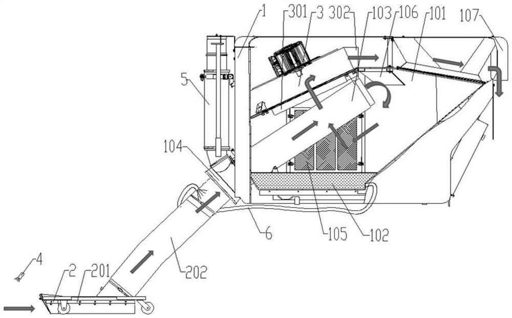
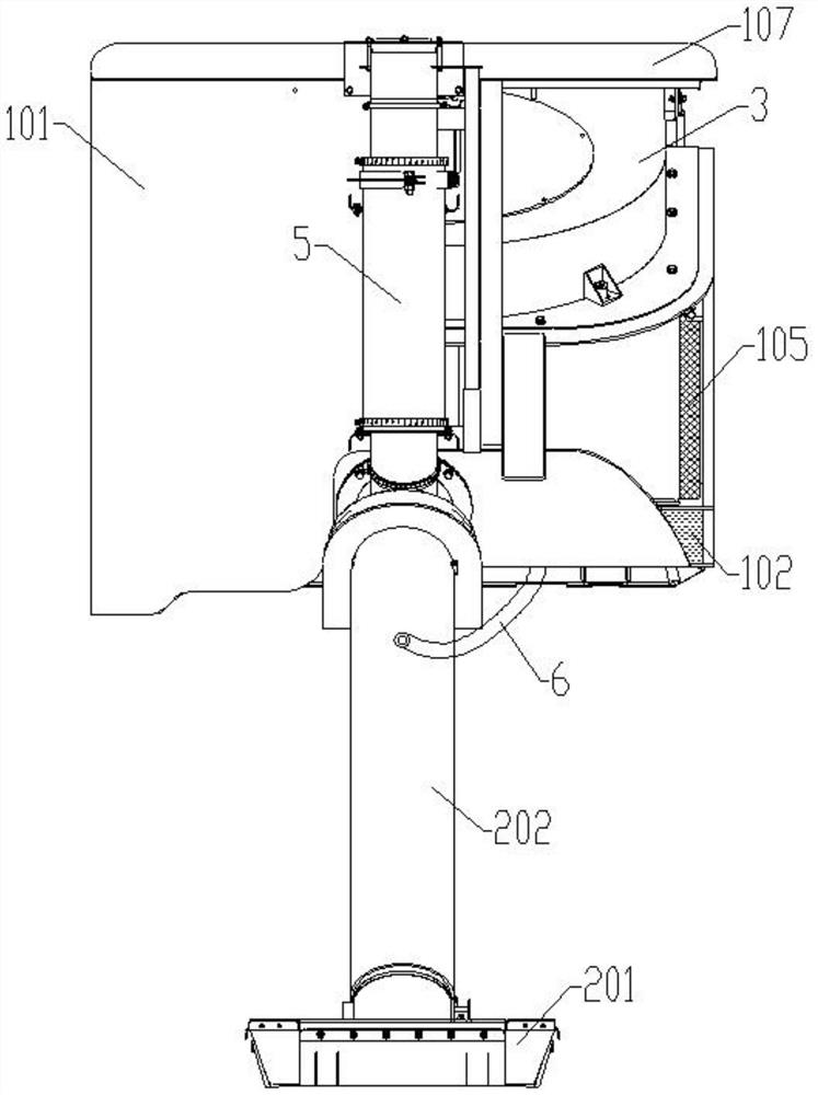
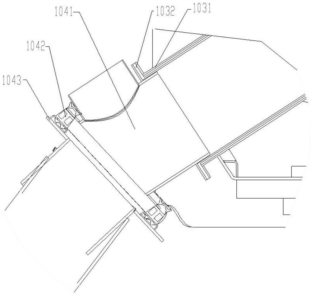
The invention discloses a pneumatic conveying system and a road sweeper with the same. The pneumatic conveying system comprises a box body, a dust collection device and a water spraying device. A dustbin is arranged in the box body, a fan is arranged at the top of the dustbin, a sewage tank is arranged at the bottom of the dustbin, filter windows are arranged on two sides of the dustbin, and the dustbin is communicated with the sewage tank through the filter windows; the dustbin is connected with the dust collection device through a main suction pipe and a transition pipe, the main suction pipe inclines from bottom to top, an inlet of the main suction pipe is connected with the transition pipe, and an outlet extends to the upper portion in the dustbin and is further provided with a flow guide baffle; a flow guide cover with a downward outlet is arranged at the top of the tail end of the box body and forms an exhaust channel with the dustbin; the sewage tank is connected to the transition pipe through a circulating pipeline; and a water sprinkling device is arranged at the front part of the dust collection device. According to the road sweeper, flying dust in the operation process can be reduced, sucked fine particle dust and the like can be prevented from being discharged again along with airflow, the influence on pedestrians and secondary pollution to the environment in the operation process are effectively avoided, and the sweeping quality of the road sweeper is improved.

Description

technical field [0001] The invention belongs to the field of sanitation vehicles, and more specifically relates to a pneumatic conveying system and a road sweeper equipped with it. Background technique [0002] Mechanized cleaning of outdoor roads is an important symbol of sanitation modernization, and road sweepers are widely used in cleaning operations in non-motorized lanes, sidewalks, squares, parks and other places due to their small size and flexible steering. At present, the common road sweepers on the market can be divided into three types according to the operation form: pure sweeping type, pure suction type and suction sweeping type. The suction-sweeping road sweeper mainly relies on the sweeping plate for cleaning, the pneumatic conveying system for garbage suction, and the negative pressure generated by the fan in the garbage box to suck in the outside air and the garbage brought in with it. However, when the garbage enters the garbage box, it will appear Part o...

Claims


Application Information

Patent Timeline
Patent Type & Authority Applications(China)
IPC IPC(8): E01H1/08B01D47/06
CPCE01H1/0827B01D47/06
Inventor 程磊单龙温玉霜冯英达肖晨邢继婉
Owner XUZHOU XUGONG ENVIRONMENTAL TECH CO LTD
Why Eureka
Try Eureka