
Tower and wind power generation device

A technology of wind turbines and towers, which is applied in the direction of wind power generation, wind engines, installation/supporting configuration of wind engines, etc. It can solve the problems of high maintenance cost, large number of bolts, heavy workload, etc., and achieve small assembly workload , Low construction cost and short assembly cycle

Pending Publication Date: 2021-12-03
张家口大金风电装备有限公司
View PDF0 Cites 0 Cited by
  • Summary
  • Abstract
  • Description
  • Claims
  • Application Information

AI Technical Summary

Problems solved by technology

The increase in the power of a single machine means that more wind energy needs to be absorbed, and the greater the load on the wind turbine, the diameter of the tower becomes larger and larger, which increases the difficulty of transportation
[0003] In order to solve the transportation problem, one way is to use on-site prefabricated steel-concrete towers, that is, on-site prefabricated concrete sections, but the existing problems of on-site prefabricated steel-concrete towers are: the workload on site is large, and there is land acquisition or lease in the concrete production site In addition, it is difficult to control the quality of concrete during on-site construction, and there are quality control risks
[0005] However, the segmented tower and the trussed tower also have the following disadvantages: 1) Both the segmented tower and the trussed tower have many components, the on-site assembly and construction workload is relatively large, the cycle is long, and the construction period is difficult to control. There are problems such as high crane costs and labor costs; 2) There are tie rods between the columns of the truss tower, and the columns and the columns and between the columns and the tie rods are connected by bolts. The number of bolts is large, and the bolts need regular maintenance. The cost is relatively high and the bolts are easy to loosen and fall, which poses a safety risk; 3) The electrical cabinets required for the wind turbine generator set of the truss tower need to be integrated in a container and placed at the bottom of the truss tower, which increases the production cost; 4 ) The cables from the bottom to the top of the truss tower, as well as the climbing aid equipment are leaked to the atmosphere, so that the cables and climbing aid equipment are easily affected by the weather environment, easy to be covered with ice, easy to aging, and prone to accidents

Method used


Image

  • Tower and wind power generation device
  • Tower and wind power generation device
  • Tower and wind power generation device

Examples


Embodiment Construction

[0044] Various aspects and features of the present application are described herein with reference to the accompanying drawings.

[0045] It should be understood that various modifications may be made to the embodiments applied for herein. Accordingly, the above description should not be viewed as limiting, but only as exemplifications of embodiments. Those skilled in the art will envision other modifications within the scope and spirit of the application.

[0046] The accompanying drawings, which are incorporated in and constitute a part of this specification, illustrate embodiments of the application and, together with the general description of the application given above and the detailed description of the embodiments given below, serve to explain the embodiments of the application. principle.

[0047]These and other characteristics of the present application will become apparent from the following description of alternative forms of embodiment given as non-limiting exam...


PUM


Abstract

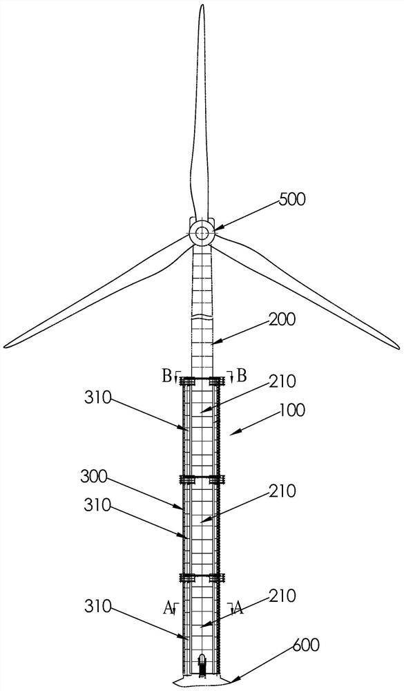
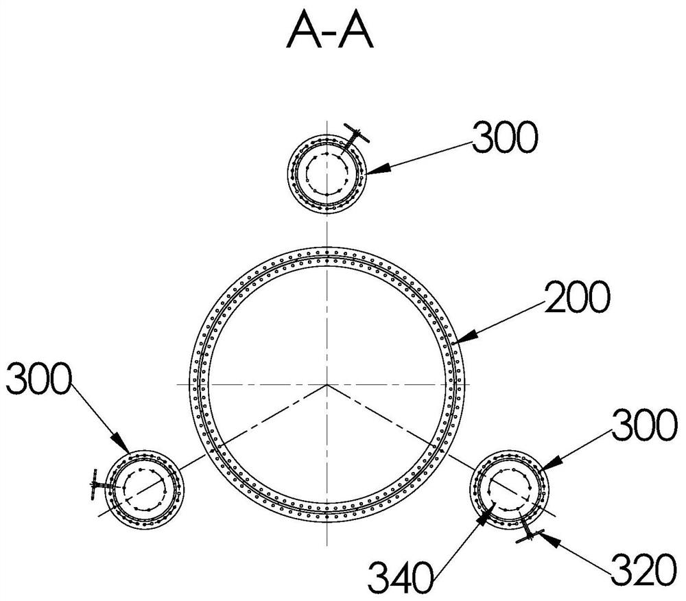
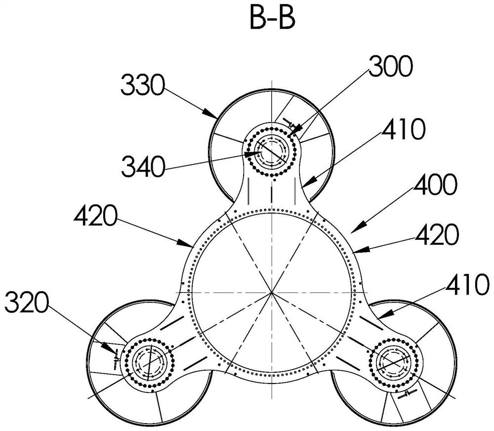
The invention discloses a tower and a wind power generation device. The tower comprises a first stand column, a plurality of second stand columns and a plurality of connecting parts, wherein the bottom end of the first stand column is used for being connected with a tower foundation, and the top end of the first stand column is used for installing a wind generating set; the plurality of second stand columns are arranged around the first stand column, the bottom ends of the second stand columns are used for being connected with the tower foundation, and the second stand columns extend in the length direction of the first stand column; and the plurality of connecting parts are sequentially arranged in the length direction of the first stand column, and the connecting parts are correspondingly connected with the first stand column and the plurality of second stand columns. The tower is convenient to transport, easy to assemble, small in on-site assembly workload, short in assembly period and low in construction cost required by assembly.

Description

technical field [0001] The present application relates to the technical field of land wind power equipment, in particular to a tower and a wind power generation device. Background technique [0002] In order to achieve parity and reduce the cost per kilowatt-hour of wind turbines, land wind turbines are developing in the direction of single-unit high-power. The increase in the power of a single machine means that more wind energy needs to be absorbed, and the load on the wind turbine is greater, resulting in an increasing diameter of the tower, which increases the difficulty of transportation. [0003] In order to solve the transportation problem, one way is to use on-site prefabricated steel-concrete towers, that is, on-site prefabricated concrete sections, but the existing problems of on-site prefabricated steel-concrete towers are: the on-site workload is large, and there is land acquisition or lease in the concrete production site In addition, it is difficult to control...

Claims


Application Information

Patent Timeline
Patent Type & Authority Applications(China)
IPC IPC(8): F03D13/20F03D80/80
CPCF03D13/20F03D80/80Y02E10/72Y02E10/728
Inventor 金鑫秦海岩庞慧茹刘金磊
Owner 张家口大金风电装备有限公司
Learn More