Oil tank structure applied to automobile transmission hydraulic system test stand

A technology of automobile transmission and hydraulic system, which is applied to the components of fluid pressure actuation system, fuel supply tank device, fluid pressure actuation device, etc., can solve the problem of poor replacement of filter equipment, poor control of oil cleanliness, and poor temperature control performance. and other problems to achieve the effect of preventing oil property change, ensuring performance and reducing qualitative change

Pending Publication Date: 2021-12-03
YINCHUAN WEILI REDUCER MACHINERY
View PDF0 Cites 0 Cited by
  • Summary
  • Abstract
  • Description
  • Claims
  • Application Information

AI Technical Summary

Problems solved by technology

[0003] The purpose of the present invention is to provide a fuel tank structure applied to the test bench of the hydraulic system of the automobile transmission, which is used to solve the technical problems of poor control of oil cleanliness, poor replaceability of filter equipment, and poor temperature control performance of the existing test bench hydraulic system

Method used


Image

  • Oil tank structure applied to automobile transmission hydraulic system test stand

Examples


Embodiment Construction

[0018] For ease of understanding, the structure of the fuel tank applied to the test bench for the hydraulic system of the automobile transmission provided by the embodiment of the present invention will be described in detail below in conjunction with the accompanying drawings.

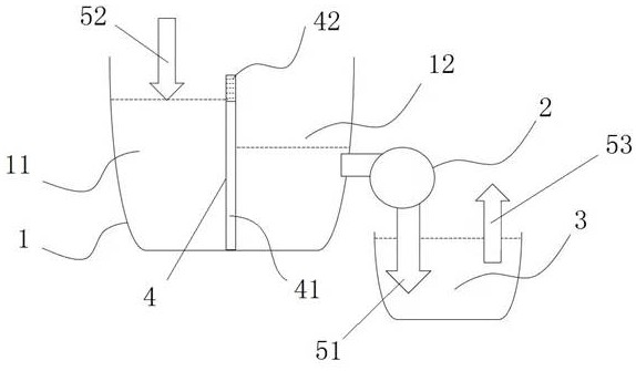
[0019] Embodiments of the present invention provide a fuel tank structure applied to a test bench for hydraulic systems of automobile transmissions, such as figure 1 As shown, it includes: a main oil tank 1, and an auxiliary oil tank 3 communicating with the main oil tank 1 through an oil pump 2; the inside of the main oil tank 1 is provided with a filter member 4 along the depth direction, and the filter member 4 separates the main oil tank 1 into a primary oil tank 11 And the secondary oil tank 12; the auxiliary oil tank 3 is provided with a temperature control assembly (not shown in the figure).

[0020] Compared with the prior art, the fuel tank structure applied to the automobile transmission hy...


PUM


Abstract

The invention discloses an oil tank structure applied to an automobile transmission hydraulic system test stand, relates to the technical field of automobile transmission hydraulic system test stands, and aims to solve the technical problems of poor oil cleanliness control, poor filter equipment replaceability and poor temperature control performance of an existing test stand hydraulic system. The oil tank structure applied to the automobile transmission hydraulic system test stand comprises a main oil tank and an auxiliary oil tank communicated with the main oil tank through an oil pump. A filtering component is arranged in the main oil tank in the depth direction and divides the main oil tank into a first-stage oil tank body and a second-stage oil tank body. The auxiliary oil tank is provided with a temperature control assembly.

Description

technical field [0001] The invention relates to the technical field of a test bench for a hydraulic system of an automobile transmission, in particular to an oil tank structure applied to a test bench for a hydraulic system of an automobile transmission. Background technique [0002] In the prior art, the oil tank of the automobile transmission hydraulic system test bench has many problems such as simple structure, simple function, poor temperature control performance, etc., and the volume of the oil tank is also large, which easily leads to oil quality denaturation. Contents of the invention [0003] The purpose of the present invention is to provide a fuel tank structure applied to the test bench of the hydraulic system of the automobile transmission, which is used to solve the technical problems of poor control of oil cleanliness, poor replaceability of filter equipment, and poor temperature control performance of the existing test bench hydraulic system . [0004] To ...

Claims


Application Information

Patent Timeline
Patent Type & Authority Applications(China)
IPC IPC(8): F15B1/26F15B21/041F15B21/042F15B21/0427
CPCF15B1/26F15B21/041F15B21/042F15B21/0427
Inventor 曹永宏李想张亮马通
Owner YINCHUAN WEILI REDUCER MACHINERY
Why Eureka
Try Eureka