Multidirectional shock absorbing and buffering device for extracting centrifugal tube in centrifugal machine and using method of multidirectional shock absorbing and buffering device
A buffer device and centrifuge tube technology, which is applied in centrifuges, springs/shock absorbers, mechanical equipment, etc., can solve problems such as mixing and inaccurate experimental data
- Summary
- Abstract
- Description
- Claims
- Application Information
AI Technical Summary
Problems solved by technology
Method used
Image

Examples
Embodiment 1
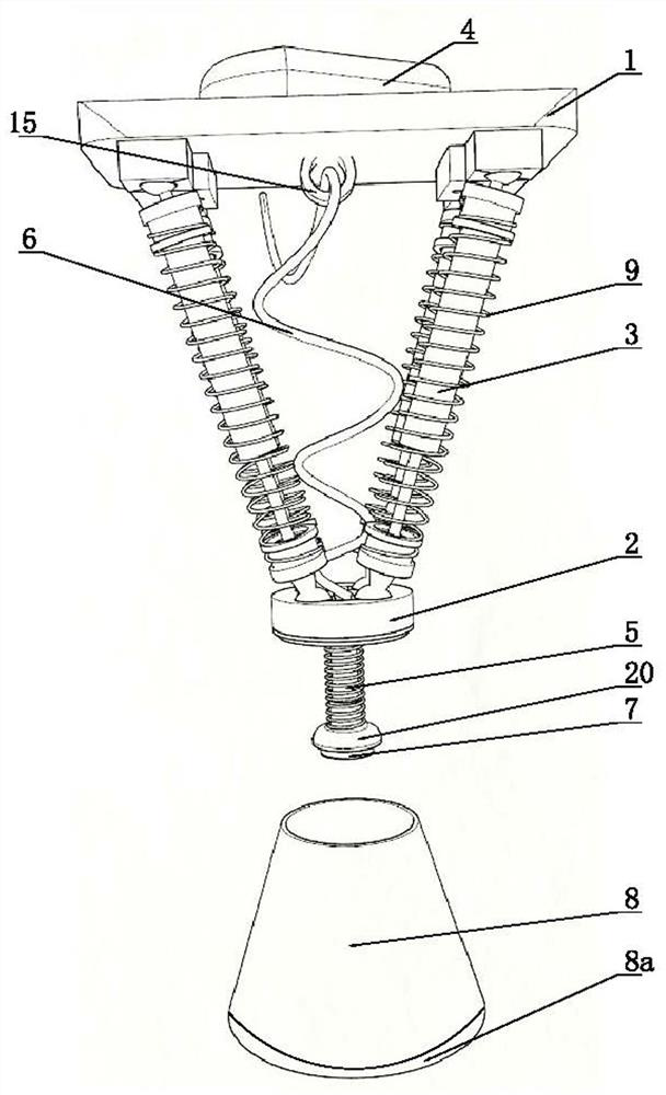
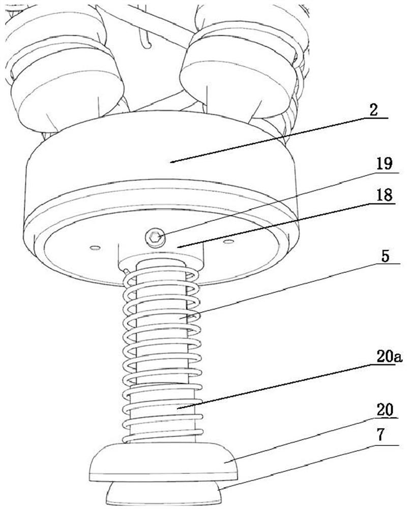
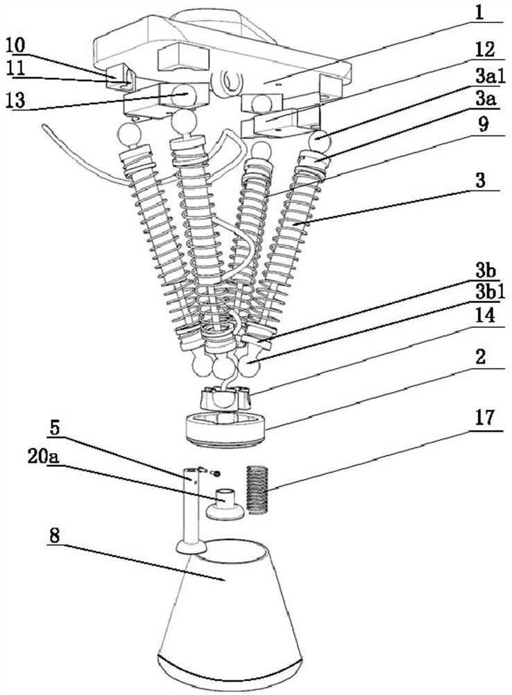
[0031] Such as Figure 1-5 As shown, it is the multi-directional shock-absorbing and buffering device for the centrifuge tube in the extraction centrifuge of this embodiment, which includes an upper fixing plate 1 and a lower installation platform 2 that are arranged correspondingly to each other. Several groups of hydraulic shock absorbers 3, the length of the hydraulic shock absorbers 3 is 14~16cm, the upper end of the upper fixing plate 1 corresponding to each hydraulic shock absorber 3 is provided with an upper mounting assembly, and the lower mounting platform 2 corresponds to each hydraulic shock absorber The lower end of the device 3 is provided with a lower installation assembly, the upper part of the upper fixed plate 1 is provided with a grip handle 4, and the middle part of the lower side of the lower installation platform 2 is provided with an air pipeline 5, and the air pipeline 5 communicates with the air hose 6. The upper end of the gas delivery hose 6 is arrang...
Embodiment 2
[0045] Such as Image 6 , and the difference with embodiment 1 is: hydraulic shock absorber 3 is provided with two groups, and two groups of hydraulic shock absorber 3 are left and right symmetrically distributed, and hydraulic shock absorber 3 is set with spring one 9, and hydraulic shock absorber 3 The upper and lower ends of the upper and lower mounting components are respectively hinged with the ball joints of the upper mounting component and the lower mounting component. Hydraulic shock absorber 3 selects the car model shock absorber of full-length about 15cm for use, and the two ends of spring one 9 are stuck in shock absorber two ends, make hydraulic shock absorber 3 when not stressed, the microhydraulic shock absorber 3 The damping piston stays in the middle of the stroke of the shock absorber. When the damping piston deviates from the middle of the stroke of the shock absorber, the spring one 9 will be stretched or contracted to generate a force in the opposite direct...
Embodiment 3
[0047] Such as Figure 7 , the difference from Embodiment 1 is that: the hydraulic shock absorber 3 is provided with three groups, the hydraulic shock absorber 3 is provided with a spring one 9, and the upper ends of the three groups of hydraulic shock absorber 3 are distributed at equal intervals along the circumferential direction and The upper installation assembly is hinged with the ball joint, and the lower ends of the three groups of hydraulic shock absorbers 3 are all arranged near the center of the lower installation platform 2 and are hinged with the lower installation assembly with the ball joint. Three sets of hydraulic shock absorbers 3 make the upper fixing plate 1 and the lower installation platform 2 form a stable connection relationship.
PUM
| Property | Measurement | Unit |
|---|---|---|
| Length | aaaaa | aaaaa |
Abstract
Description
Claims
Application Information
 - R&D
- Intellectual Property
- Life Sciences
- Materials
- Tech Scout
- Unparalleled Data Quality
- Higher Quality Content
- 60% Fewer Hallucinations
Browse by: Latest US Patents, China's latest patents, Technical Efficacy Thesaurus, Application Domain, Technology Topic, Popular Technical Reports.
© 2025 PatSnap. All rights reserved.Legal|Privacy policy|Modern Slavery Act Transparency Statement|Sitemap|About US| Contact US: help@patsnap.com