Robot system for bridge vibration detection
A robotic system and vibration detection technology, applied in radio wave measurement systems, control/regulation systems, instruments, etc., can solve the problems of long test cycle, large human, material and financial resources, and difficult operation, and achieve high speed and practicality. The effect of sex, obstacle crossing convenience
- Summary
- Abstract
- Description
- Claims
- Application Information
AI Technical Summary
Problems solved by technology
Method used
Image
Examples
Embodiment 1
[0045] A robot system for bridge vibration detection, including a robot body and a detection component installed on the robot body;
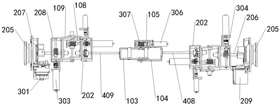
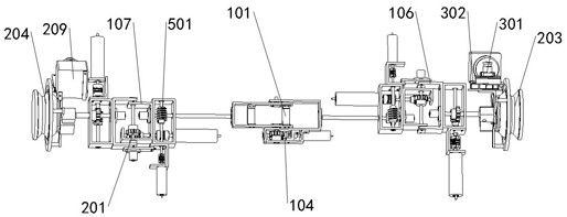
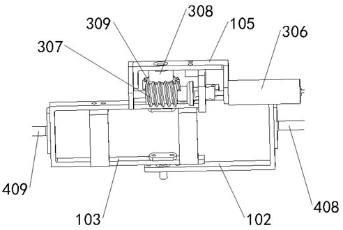
[0046] Such as figure 1 , 2 , 3, the robot body includes a main joint assembly 101, an auxiliary joint assembly and an adsorption assembly, and the main joint assembly 101 includes a first connecting block 102, a second connecting block 103, a first rotating mechanism 104, a first fixed frame 105, the first connecting block 102 and the second connecting block 103 are rotatably connected together through a first rotating mechanism 104, and the first rotating mechanism 104 is fixed on the first connecting block 102 through a first fixing frame 105 superior;
[0047] Such as figure 1 , 2 , 4, the auxiliary joint assembly includes a first auxiliary joint mechanism 106 and a second auxiliary joint mechanism 107, the first auxiliary joint mechanism 106 is mated and connected to the first connecting block 102 of the main joint assembly 101, The se...
Embodiment 2
[0060] The second aspect of the present invention provides a vibration detection method, which is applied to any one of the robot systems for bridge vibration detection, including the following steps:
[0061] S102, collect the vibration acceleration in the three directions of the bridge X, Y, and Z axes through the first detector , , ; At the same time, the vibration acceleration of the single axis of the bridge is collected by the second detector ; Among them, the time interval between two adjacent acquisitions is , The time is greater than 1s;
[0062] S104, through the collected , , Obtain the vibration velocity in the three directions of X, Y, and Z axes , , ; through the collected Get the uniaxial vibration velocity ;
[0063] It should be noted that, through the collected , , Obtain the vibration velocity in the three directions of X, Y, and Z axes , , , whose calculation formula is:
[0064]
[0065]
[0066]
[0067] i...
Embodiment 3
[0098] The third aspect of the present invention provides a robot obstacle avoidance method, which is applied to any one of the robot systems for bridge vibration detection, including the following steps:
[0099] Obtain obstacle information simultaneously by using ultrasonic detectors and camera mechanisms;
[0100] Processing the obstacle information obtained by the camera mechanism to obtain the depth information of the obstacle; processing the obstacle information obtained by the ultrasonic detector to obtain obstacle distance information;
[0101] The specific steps of processing the obstacle information obtained by the camera mechanism to obtain the depth information of the obstacle include:
[0102] Obtain the first-angle video and second-angle video of obstacles through the camera mechanism;
[0103] Processing the first-angle video and the second-angle video to obtain each frame of the first-angle obstacle picture corresponding to the first-angle video and each frame...
PUM
 Abstract
Description
Claims
Application Information
 - R&D
- Intellectual Property
- Life Sciences
- Materials
- Tech Scout
- Unparalleled Data Quality
- Higher Quality Content
- 60% Fewer Hallucinations
Browse by: Latest US Patents, China's latest patents, Technical Efficacy Thesaurus, Application Domain, Technology Topic, Popular Technical Reports.
© 2025 PatSnap. All rights reserved.Legal|Privacy policy|Modern Slavery Act Transparency Statement|Sitemap|About US| Contact US: help@patsnap.com


