Vacuum circuit breaker and supporting conductor structure thereof
A technology of vacuum circuit breaker and conductor structure, which is applied to high-voltage air circuit breakers, circuits, electrical components, etc., can solve the problems of inability to release heat and affect the mechanical properties of vacuum interrupters, so as to improve the natural heat exchange capacity and ensure mechanical characteristics and insulation characteristics, the effect of increasing the heat dissipation area
- Summary
- Abstract
- Description
- Claims
- Application Information
AI Technical Summary
Problems solved by technology
Method used
Image
Examples
Embodiment 1
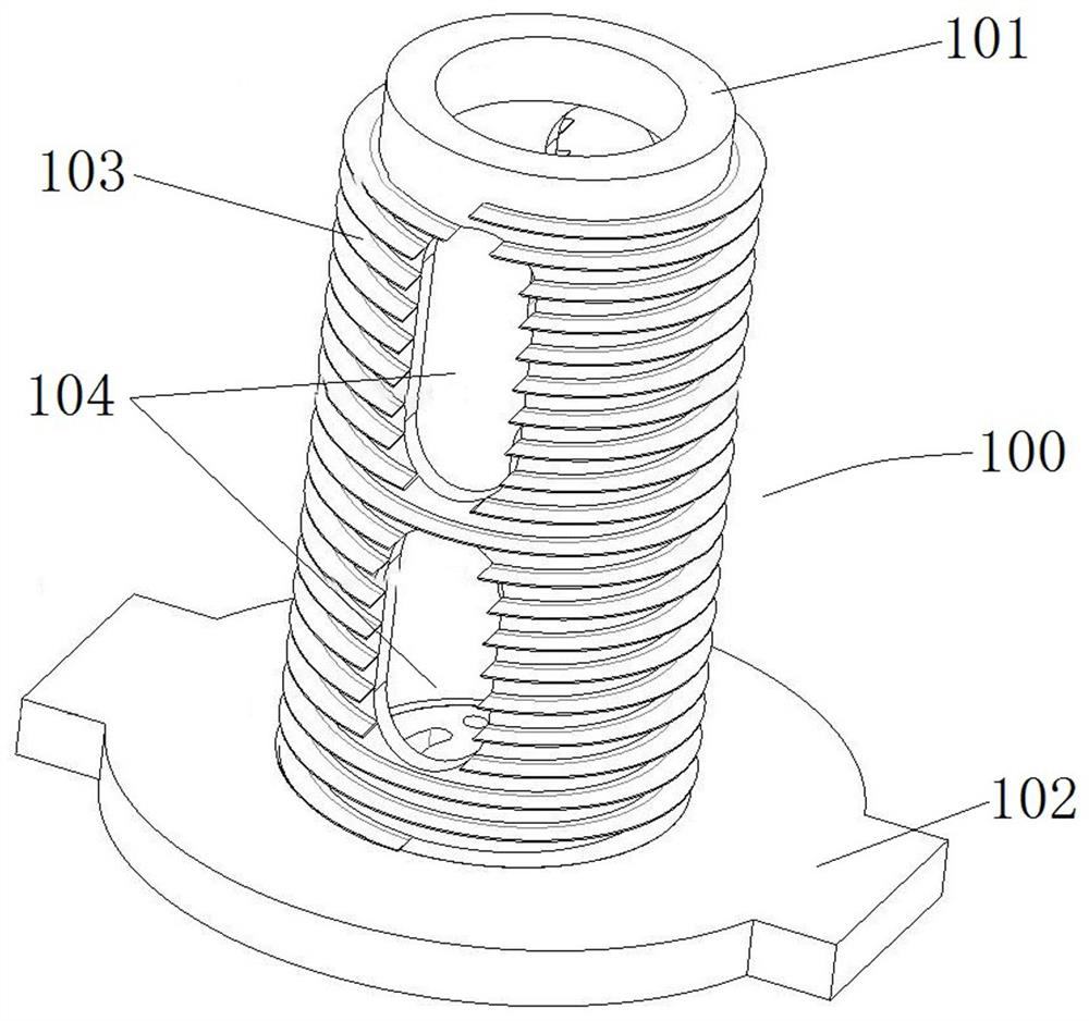
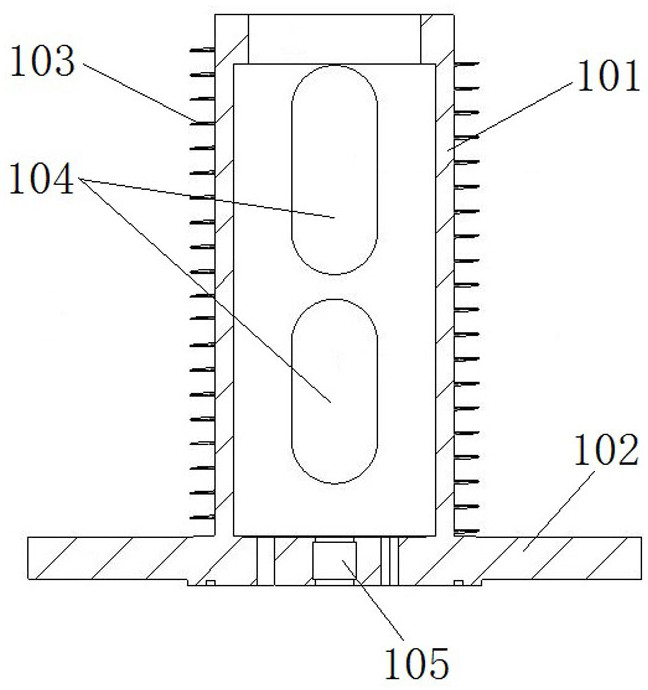
[0040] like figure 1 and figure 2As shown, the main components of the supporting conductor structure of the vacuum circuit breaker (hereinafter referred to as the supporting conductor structure 100) include a conductive support cylinder 101, a lower conductive seat 102 and a spiral fin 103, and the conductive support cylinder 101 and the lower conductive seat 102 are both conductor.
[0041] The conductive support cylinder 101 is a cylinder that penetrates up and down. The upper end is used to support the vacuum interrupter upward. When in use, the conductive rod at the movable end penetrates into the conductive support cylinder 101. Usually, there is a gap between the conductive rod at the movable end and the conductive support cylinder 101. The spring contact finger ensures the conductive connection between the conductive support cylinder 101 and the conductive rod at the moving end. The lower conductive base 102 is arranged at the lower end of the conductive support cyli...
specific Embodiment 2
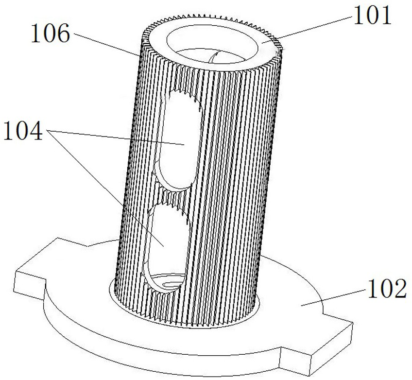
[0047] like image 3 As shown, the difference from Embodiment 1 is that in Embodiment 1, the heat dissipation fins are spiral fins. In this embodiment, the heat dissipation fins are vertical fins 106, and the vertical fins 106 are along the The axial extension of 101, the specific extension length can be determined according to the required heat dissipation capacity, and there are a plurality of vertical fins 106 arranged at intervals along the circumference of the conductive support cylinder 101, the number of which is changed according to the actual situation, but at least there are two. The heat exchange capacity of the conductive support cylinder 101 can be improved by adding vertical fins 106 . The structure of the lower conductive base 102 and the radial hole 104 is the same as that of the first embodiment.
specific Embodiment 3
[0049] like Figure 4 and Figure 5 As shown, the difference from Embodiment 1 is that in Embodiment 1, the heat dissipation fins are spiral fins. In this embodiment, the heat dissipation fins are annular fins 107, and the annular fins 107 are the same Shaft arrangement, the annular fins 107 are arranged at intervals along the axial direction of the conductive support cylinder 101, and the number varies according to actual conditions, but there are at least two. The structure of the lower conductive base 102 and the radial hole 104 is the same as that of the first embodiment.
PUM
 Abstract
Description
Claims
Application Information
 - R&D
- Intellectual Property
- Life Sciences
- Materials
- Tech Scout
- Unparalleled Data Quality
- Higher Quality Content
- 60% Fewer Hallucinations
Browse by: Latest US Patents, China's latest patents, Technical Efficacy Thesaurus, Application Domain, Technology Topic, Popular Technical Reports.
© 2025 PatSnap. All rights reserved.Legal|Privacy policy|Modern Slavery Act Transparency Statement|Sitemap|About US| Contact US: help@patsnap.com


