
Four-electrode self-triggering steepening gas switch

A gas switch and self-triggering technology, which is applied to electrical components, spark gaps with auxiliary triggering devices, circuits, etc., can solve the problems affecting the stability of the switch's self-breakdown voltage, the slowing down of the output front of the pulse power source, and the stability of the switch's pre-ionization In order to achieve the effects of stable switching characteristics, optimized electric field distribution, and long service life of switching characteristics

Active Publication Date: 2021-12-03
XI AN JIAOTONG UNIV +1
View PDF3 Cites 0 Cited by
  • Summary
  • Abstract
  • Description
  • Claims
  • Application Information

AI Technical Summary

Problems solved by technology

[0003] The existing self-triggering steepening gas switch mostly adopts multi-gap structure or Trigatron type structure. The multi-gap structure self-triggering steepening gas switch has a long gap and a large overall inductance, which slows down the output frontier of the pulse power source and affects the output performance; Trigatron type The structure self-triggering steepens the switch, and the discharge of the trigger gap will cause the ablation of the insulating material between the trigger electrode and the main electrode, and the stability of the pre-ionization of the switch will be reduced, thereby affecting the stability of the self-breakdown voltage of the switch

Method used


Image

  • Four-electrode self-triggering steepening gas switch
  • Four-electrode self-triggering steepening gas switch
  • Four-electrode self-triggering steepening gas switch

Examples


Embodiment Construction

[0036] The following will clearly and completely describe the technical solutions in the embodiments of the present invention with reference to the accompanying drawings in the embodiments of the present invention. Obviously, the described embodiments are some of the embodiments of the present invention, but not all of them. Based on the embodiments of the present invention, all other embodiments obtained by persons of ordinary skill in the art without making creative efforts belong to the protection scope of the present invention.

[0037] In describing the present invention, it should be understood that the terms "center", "longitudinal", "transverse", "upper", "lower", "front", "rear", "left", "right", " The orientation or positional relationship indicated by "vertical", "horizontal", "top", "bottom", "inner", "outer", "side", "end", "side" etc. is based on the Orientation or positional relationship is only for the convenience of describing the present invention and simplif...


PUM


Abstract

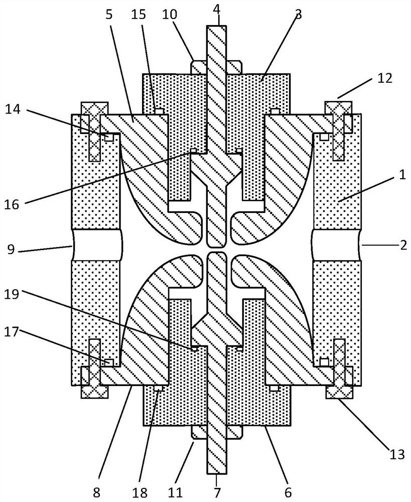
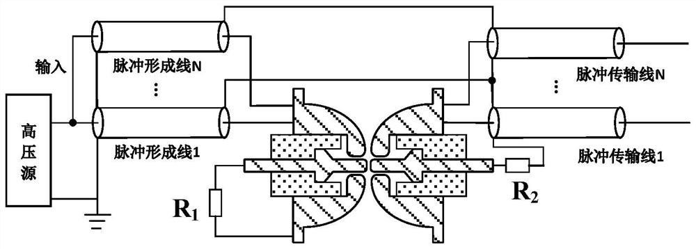
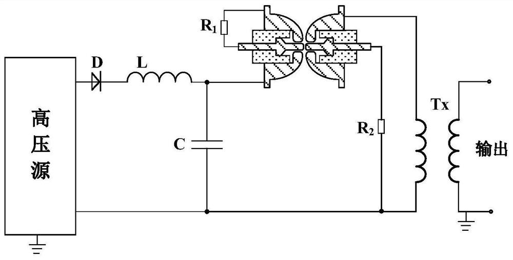
The invention discloses a four-electrode self-triggering steepening gas switch which is characterized in that an upper electrode is arranged at the upper part of an insulating sleeve, an upper intermediate electrode sleeves the upper electrode, an upper insulating flange is arranged between the upper electrode and the upper intermediate electrode, and sealing gaskets are respectively arranged between the upper insulating flange and the upper electrode and between the upper insulating flange and the upper intermediate electrode; a lower electrode corresponding to the upper electrode is arranged at the lower part of the insulating sleeve, a lower intermediate electrode sleeves the lower electrode, a lower insulating flange is arranged between the lower electrode and the lower intermediate electrode, and sealing gaskets are respectively arranged between the lower insulating flange and the lower intermediate electrode and between the lower insulating flange and the lower electrode; and an air inlet is formed in one side of the insulating sleeve, and an air outlet is formed in the other side correspondingly. According to the four-electrode self-triggering steepening gas switch, the gap of the two intermediate electrodes is firstly broken down to further assist the breakdown of a main gap, the breakdown between the electrodes does not ablate the internal insulating material, the switch can operate in a repetition frequency mode, the switch is stable in working property and long in service life, the structure is compact, and the conduction inductance is low.

Description

technical field [0001] The invention belongs to the technical field of gas switches, in particular to a four-electrode self-triggering steepening gas switch. Background technique [0002] The gas switch is a key component connecting the capacitive energy storage device and the load in the pulse power source, and its working characteristics determine the output performance of the pulse power source. The development of high-stability, high-repetition-frequency pulse power sources requires gas switches to have stable breakdown performance and repeat-frequency operation capabilities. Generally, switches adopt two operating modes: external triggering and self-triggering steepening. Among them, the external trigger mode adds an external trigger unit to make it precisely cooperate with the pulse power source. At a certain moment, the external trigger unit outputs a trigger pulse to realize the gas switch conduction and the output of the pulse power source. It increases the difficu...

Claims


Application Information

Patent Timeline
Patent Type & Authority Applications(China)
IPC IPC(8): H01T2/00
CPCH01T2/00
Inventor 杨兰均张永鹏刘帅路志建
Owner XI AN JIAOTONG UNIV
Learn More