
Device for preventing deviation in circular steel pipe cutting process

A steel pipe and circular technology, which is applied in the field of anti-deviation devices, can solve the problems of steel pipe cutting position deviation, fatigue, and the impact of operator work efficiency, and achieve the effect of improving work efficiency

Inactive Publication Date: 2021-12-07
上海聚胺机械设备有限公司
View PDF0 Cites 0 Cited by
  • Summary
  • Abstract
  • Description
  • Claims
  • Application Information

AI Technical Summary

Problems solved by technology

[0006] Aiming at the deficiencies of the prior art, the present invention provides a device for preventing deviation during the cutting process of circular steel pipes, which has the advantages of being able to automatically fix the steel pipes effectively and automatically perform cutting operations on the steel pipes, and solves the problem that the operator is very It is seldom to fix the steel pipe, so it is easy to cause the cutting position of the steel pipe to shift, then the cutting operation needs to be performed again, which affects the work efficiency of the operator, and the operator needs to do it himself every time To complete, this will make the operator feel very tired after the work is completed

Method used


Image

  • Device for preventing deviation in circular steel pipe cutting process
  • Device for preventing deviation in circular steel pipe cutting process
  • Device for preventing deviation in circular steel pipe cutting process

Examples


Embodiment 1

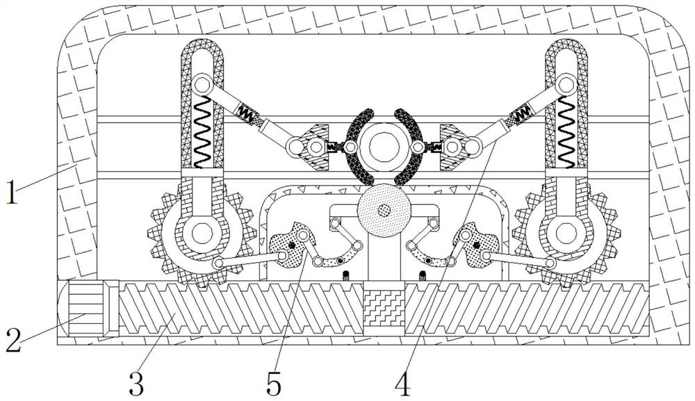
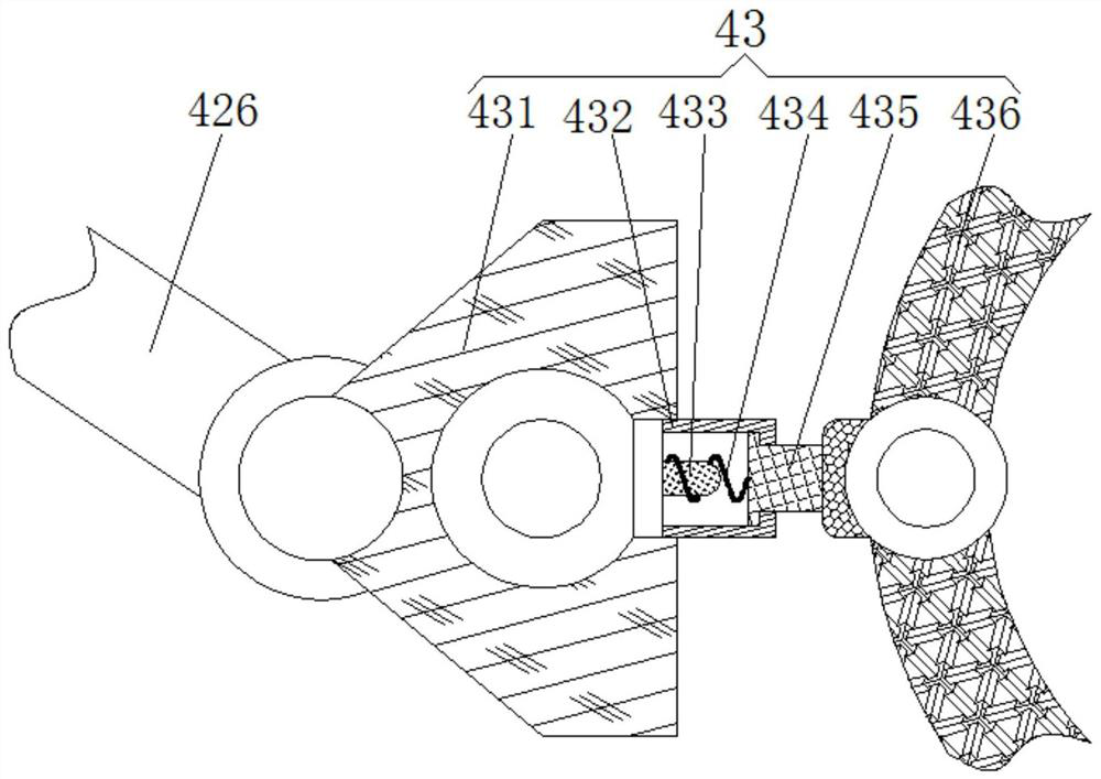
[0025] see Figure 1-3 , a device for preventing deviation during the cutting process of circular steel pipes, comprising a casing 1, a motor-2 is fixedly connected to the inside of the casing 1, a screw 3 is fixedly connected to the outside of the motor-2, and a fixing mechanism is movably connected to the outside of the screw 3 4. The fixing mechanism 4 includes a rotating wheel 41 , a rotating assembly 42 capable of being driven by the rotating wheel 41 , and a fixing assembly 43 capable of fixing the steel pipe.

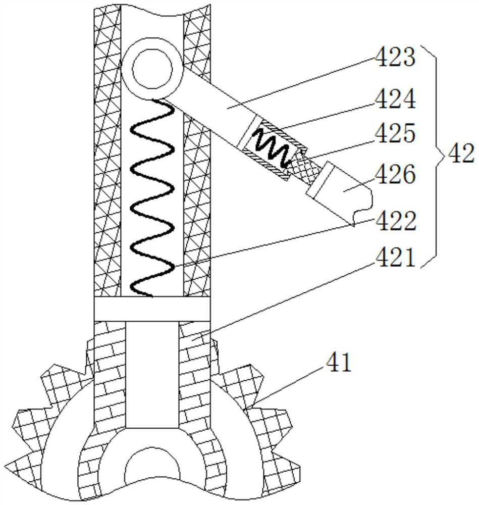
[0026] Rotation assembly 42 comprises fixed frame 421, connecting spring one 422, rotating plate one 423, connecting spring two 424, slide bar 425, rotating plate two 426, and rotating wheel 41 engagement is connected in the outside of screw rod 3, and fixed frame 421 is fixedly connected in the rotating On the outside of the wheel 41, the connecting spring one 422 is fixedly connected inside the fixed frame 421, the rotating plate one 423 is movably connected in...

Embodiment 2

[0029] see Figure 4 , the inside of the housing 1 is movably connected with a cutting mechanism 5, the cutting mechanism 5 includes a fixed groove 51, a movable assembly 52 that can be driven by the rotating wheel 41, and a lifting assembly 53 that can be lifted by the movable assembly 52, and the fixed groove 51 is fixedly connected to the casing 1 internal.

[0030] The movable assembly 52 comprises a transmission rod 521, a fixed shaft one 522, a rotating disk 523, and a connecting rod one 524. The transmission rod 521 is movably connected to the outside of the rotating wheel 41, the fixed shaft one 522 is fixedly connected to the inside of the fixed groove 51, and the rotating disk 523 The rotation is connected to the outside of the fixed shaft 1 522, the connecting rod 1 524 is movably connected to the outside of the rotating disk 523, and the end of the transmission rod 521 away from the rotating wheel 41 is movably connected to the outside of the rotating disk 523.

...

Embodiment 3

[0033] see Figure 1-4 , a device for preventing deviation during the cutting process of circular steel pipes, comprising a casing 1, a motor-2 is fixedly connected to the inside of the casing 1, a screw 3 is fixedly connected to the outside of the motor-2, and a fixing mechanism is movably connected to the outside of the screw 3 4. The fixing mechanism 4 includes a rotating wheel 41 , a rotating assembly 42 capable of being driven by the rotating wheel 41 , and a fixing assembly 43 capable of fixing the steel pipe.

[0034] Rotation assembly 42 comprises fixed frame 421, connecting spring one 422, rotating plate one 423, connecting spring two 424, slide bar 425, rotating plate two 426, and rotating wheel 41 engagement is connected in the outside of screw rod 3, and fixed frame 421 is fixedly connected in the rotating On the outside of the wheel 41, the connecting spring one 422 is fixedly connected inside the fixed frame 421, the rotating plate one 423 is movably connected in...


PUM


Abstract

The invention relates to the technical field of electromechanical machinery, and discloses a device for preventing deviation in a circular steel pipe cutting process. The device comprises a shell, a first motor is fixedly connected inside the shell, a screw rod is fixedly connected outside the first motor, a fixing mechanism is movably connected outside the screw rod, a fixing mechanism comprises a rotating wheel, a rotating assembly capable of being driven by the rotating wheel and a fixing assembly capable of fixing a steel pipe. The first motor rotates to drive the screw rod to rotate, the screw rod rotates to drive the rotating wheel to rotate, then a fixing frame is driven to rotate, a square plate is made to move while the fixing frame rotates, accordingly, an arc-shaped clamping plate is driven to move, a circular steel pipe can be fixed by the arc-shaped clamping plate, the situation that the position of the circular steel pipe deviates in the cutting process, the cut steel pipe does not meet the production requirements is avoided, and therefore, the working efficiency of cutting the steel pipe is greatly improved.

Description

technical field [0001] The invention relates to the technical field of electromechanical machinery, in particular to a device for preventing deviation during cutting of circular steel pipes. Background technique [0002] Electromechanical equipment generally refers to machinery, electrical appliances, and electrical automation equipment. In construction, it refers to the general term for machinery and pipeline equipment other than geotechnical, carpentry, steel bars, and muddy water. It is different from hardware and mostly refers to finished products that can achieve certain functions. [0003] As a necessity in the construction industry in life, steel pipes need to be classified and cut into different lengths for use in various situations. The traditional cutting method is that the operator first places the steel pipe on the cutting machine, and then manually cuts the cutting machine. Press down to cut the steel pipe. During such an operation, the steel pipe is rarely fix...

Claims


Application Information

Patent Timeline
Patent Type & Authority Applications(China)
IPC IPC(8): B23D21/00B23D33/00B23D33/02
CPCB23D33/02B23D21/00B23D33/00
Inventor 黄冬娣
Owner 上海聚胺机械设备有限公司
Learn More