


Quick Research
Generate reliable direction feasibility study reports for your R&D in just a few steps.

Technical Q&A
Discover and master advanced knowledge NOW. Basics, ideas, possibilities, all at once.

Find Solutions
As an expert in R&D theories, this can generate solutions to your technical problems instantly.

Evaluate Feasibility
Analyze your overall solution with one click, know your potential R&D risks in advance.

Monitor Landscape
Get weekly tech updates, stay abreast of the latest tech innovations and key insights.
Tab welding method, battery cell tab and battery
A pole-ear welding and pole-ear technology, which is applied in the manufacture of primary batteries, welding equipment, and secondary batteries, can solve the problems of poor overcurrent capability at the laser welding position, weakened overcurrent capability at the welding position, and insufficient tensile strength. , to achieve the effect of strong overcurrent capability, small internal resistance and high reliability
- Summary
- Abstract
- Description
- Claims
- Application Information
AI Technical Summary
Problems solved by technology
Method used
Image

Examples
Embodiment 1
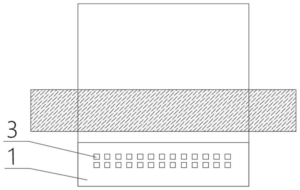
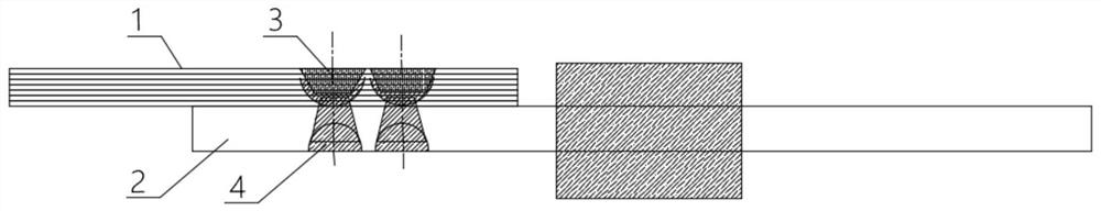
[0045] Such as figure 1 As shown, this embodiment provides a tab welding method for connecting tabs in pouch batteries. The tab welding method includes the following steps:
[0046] S1. Ultrasonic pre-welding is performed on the first side of the first welding zone of the tab foil 1 .
[0047] That is, firstly, the first side of the first welding zone of the tab foil 1 is ultrasonically welded. Specifically, the first side of the first welding area of the tab foil 1 is pre-welded with the ultrasonic welding head, and the welding position is shaped to make the surface of the welding position smooth, which is convenient for subsequent air gap removal and welding, It is beneficial to improve the welding strength and improve the welding quality. Preferably, in this embodiment, the size of the welding head used for ultrasonic pre-welding of the tab foil 1 is 0.2mm*0.2mm, and the distance between two adjacent welding points is 0.5mm. The welding head of this size and The distan...
Embodiment 2
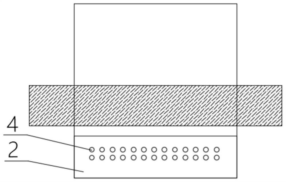
[0070] This embodiment also provides a tab welding method for the connection of tabs in pouch batteries. The difference between this embodiment and Embodiment 1 is that: Figure 4 As shown, the main laser welding is a strip-shaped laser welding, that is, the main laser welding forms a strip-shaped second welding scar 5 on the first side of the welding area of the metal strip 2 .
[0071] Preferably, the welding point center of laser main welding moves along the line connecting the welding spot 3 centers of ultrasonic welding main welding, and the welding path of laser main welding passes through the center of welding spot 3 of ultrasonic welding main welding, which can make the second welding scar The projection of 5 on the first side of the tab foil 1 passes through the first welding scar 3, and the materials at the second welding scar 5 and the first welding scar 3 can be fully fused together, further improving the welding strength and welding quality.
[0072] This embodi...
PUM
 Abstract
Description
Claims
Application Information
 - R&D Engineer
- R&D Manager
- IP Professional
- Industry Leading Data Capabilities
- Powerful AI technology
- Patent DNA Extraction
Browse by: Latest US Patents, China's latest patents, Technical Efficacy Thesaurus, Application Domain, Technology Topic, Popular Technical Reports.
© 2024 PatSnap. All rights reserved.Legal|Privacy policy|Modern Slavery Act Transparency Statement|Sitemap|About US| Contact US: help@patsnap.com