
Material suction channel of split type vacuum material suction machine

A vacuum suction machine, split-type technology, applied in the field of suction machines, can solve the problems of inconvenient assembly of the suction pipe and external pipes, cumbersome and time-consuming disassembly operations, and falling off of external pipes, so as to achieve convenient disassembly and assembly and avoid safety accidents , Increase the effect of frictional resistance

Pending Publication Date: 2021-12-07
泰州市科飞橡塑机械有限公司
View PDF0 Cites 0 Cited by
  • Summary
  • Abstract
  • Description
  • Claims
  • Application Information

AI Technical Summary

Problems solved by technology

[0002] With the development of industry, the application of plastic products has spread all over the fields of industry, agriculture and daily life, and the production of plastic products is generally carried out by injection molding machines or extruders. In the past, materials were fed directly by hand, and the efficiency was relatively low. With the advancement of science and technology, modern production workshops generally use suction machines for feeding;
[0003] At present, the suction pipe of the vacuum suction machine needs to be used in combination with an external pipe, but the traditional suction pipe and the external pipe are inconvenient to assemble, the disassembly operation is cumbersome and time-consuming, and the external pipe is easy to fall off. Therefore, we propose a split vacuum The suction channel of the suction machine

Method used


Image

  • Material suction channel of split type vacuum material suction machine
  • Material suction channel of split type vacuum material suction machine
  • Material suction channel of split type vacuum material suction machine

Examples


Embodiment 1

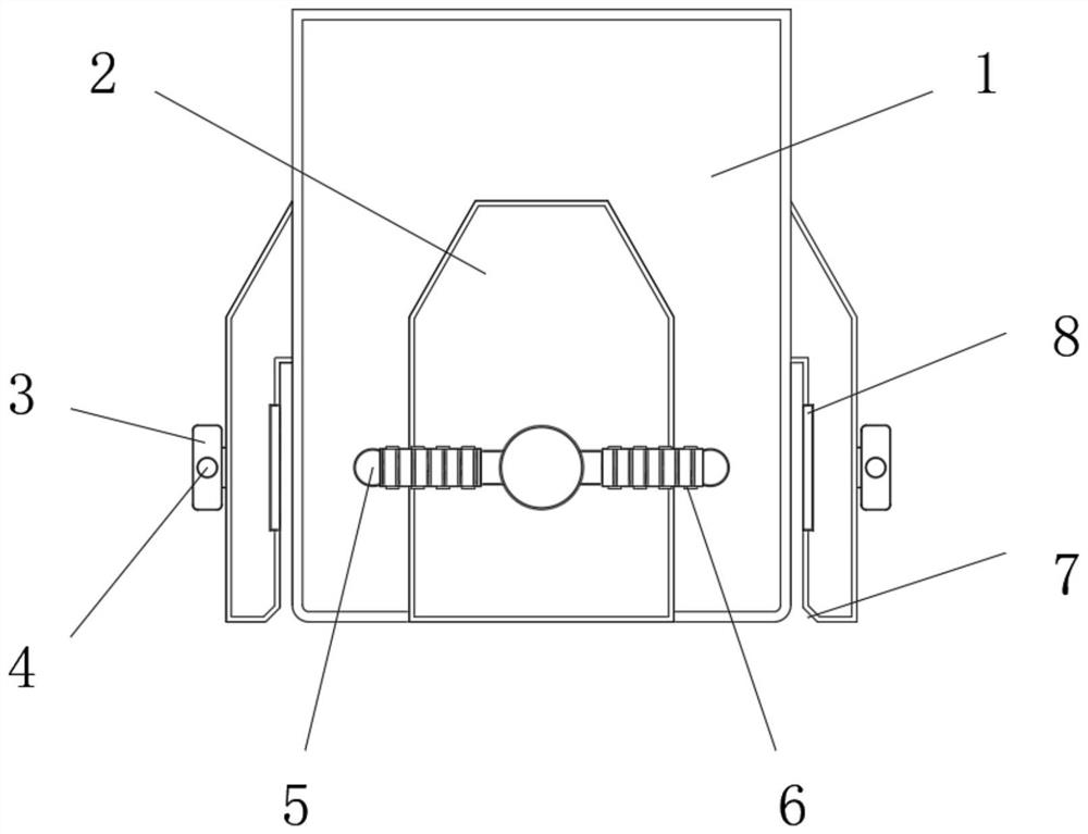
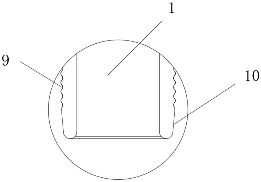
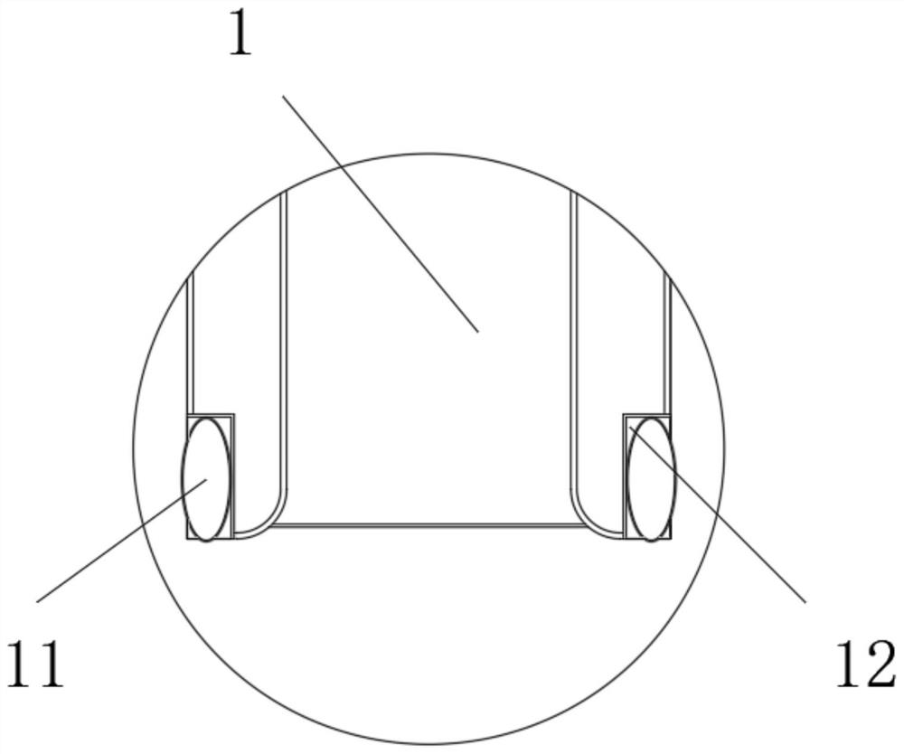
[0029] Please refer to figure 1 , Figure 4 with Figure 5 As shown, the present invention provides a suction channel of a split-type vacuum suction machine, including a suction pipe 1, the outer wall of the suction pipe 1 is radially connected with a fixed seat 2, and the inner wall of the front end of the fixed seat 2 is connected to the suction pipe. The side outer wall of the pipe 1 forms a clamping groove, and the fixing seat 2 is provided with a pressing part 15 on the surface of the clamping groove, and the pressing part 15 is threadedly connected with the fixing seat 2. The plate 20 and the base plate 16 are elastically connected. The suction pipe 1 of the split vacuum suction machine must be used in combination with an external pipe. 2 along the radial direction of the suction pipe 1 is conducive to the fixation and stability of the external pipe. The pressing part 15 inside the clamping groove resists and compresses the external pipe to ensure that the assembly of ...

Embodiment 2

[0034] This embodiment is an improvement made on Embodiment 1. For details, please refer to figure 1 with Figure 4 , the midpoint of the inner end of the pressing member 15 is connected with a screw 14, the outer wall of the fixing seat 2 is provided with a threaded hole 13 relative to the screw 14, and the end of the screw 14 runs through the threaded hole 13 and is connected with a knob 3. The outer wall of the rod 14 and the inner wall of the threaded hole 13 are screwed together, the pressing part 15 is assembled with the screw rod 14, the screw rod 14 rotates in or out relative to the screw hole 13, and the screw rod 14 pushes and compresses The space between the parts 15 is adjusted relative to the clamping groove, the pressing part 15 is suitable for external pipes of various specifications and wall thicknesses, and the knob 3 is conducive to the rotation control of the screw mandrel 14.

[0035] Such as figure 1 As shown, the present invention discloses that the sid...

Embodiment 3

[0037] This embodiment is an improvement made on Embodiment 1. For details, please refer to Figure 4 with Figure 5 , the base plate 16 is fixed on the end of the screw rod 14, and the backing plate 20 covers and is arranged on the outer end surface of the base plate 16, and a large spring 17 is laid symmetrically between the interlayer of the base plate 16 and the backing plate 20, and the backing plate 20 of the pressing member 15 and the The large spring 17 between the base plate 16 of the pressing part 15 can be deformed and there is a certain buffer, which is conducive to the matching of the external pipe and the pressing part 15. At the same time, the large spring 17 ensures that the pressing part 15 exerts a continuous and stable force on the external pipe , The uniform and symmetrical laying of the large spring 17 ensures that the pressing member 15 exerts a continuous and stable force on the external pipe.

[0038] Such as Figure 4 As shown, the present invention ...


PUM


Abstract

The invention discloses a material suction channel of a split type vacuum material suction machine. The material suction channel of the split type vacuum material suction machine comprises a material suction pipe, the outer wall of the material suction pipe is radially connected with a fixing seat in a surrounding mode, a clamping groove is formed by the inner wall of the front end of the fixing seat and the outer wall of the side face of the material suction pipe, and a pressing piece is arranged on the clamping groove face of the fixing seat, the pressing piece is in threaded connection with the fixing seat, the pressing piece comprises a base plate and a base plate, and the base plate is elastically connected with the base plate; an external pipeline is inserted into the clamping groove formed by the fixing seat and the material suction pipe, the pressing piece in the clamping groove abuts against and presses the external pipeline, the threaded connection between the pressing piece and the fixing seat facilitates adjustment of the distance between the pressing piece and the fixing seat, and the pressing piece is suitable for the external pipelines of various specifications and wall thicknesses, elastic connection between the pressing pieces is beneficial to existence of a certain deformation space in the abutting pressing process of the pressing pieces, insertion assembly between the external pipeline and the clamping groove is facilitated, and meanwhile it is guaranteed that the pressing pieces apply force to the external pipeline continuously and stably through the elastic connection.

Description

technical field [0001] The invention relates to the technical field of suction machines, in particular to a suction channel of a split-type vacuum suction machine. Background technique [0002] With the development of industry, the application of plastic products has spread all over the fields of industry, agriculture and daily life, and the production of plastic products is generally carried out by injection molding machines or extruders. In the past, materials were fed directly by hand, and the efficiency was relatively low. With the advancement of science and technology, modern production workshops generally use suction machines for feeding; [0003] At present, the suction pipe of the vacuum suction machine needs to be used in combination with an external pipe, but the traditional suction pipe and the external pipe are inconvenient to assemble, the disassembly operation is cumbersome and time-consuming, and the external pipe is easy to fall off. Therefore, we propose a s...

Claims


Application Information

Patent Timeline
Patent Type & Authority Applications(China)
IPC IPC(8): B29C31/04
CPCB29C31/04
Inventor 韩智辉
Owner 泰州市科飞橡塑机械有限公司
Learn More