Layer moving type large-stroke six-degree-of-freedom heavy-load installation vehicle
A technology with a large stroke and an installation vehicle, which is applied to cranes, motor vehicles, vehicle parts, etc., can solve the problems of complex structure, poor generalization, and poor maneuverability, and achieve good folding performance, high maneuverability, and low cost. low effect
- Summary
- Abstract
- Description
- Claims
- Application Information
AI Technical Summary
Problems solved by technology
Method used
Image
Examples
specific Embodiment approach 1
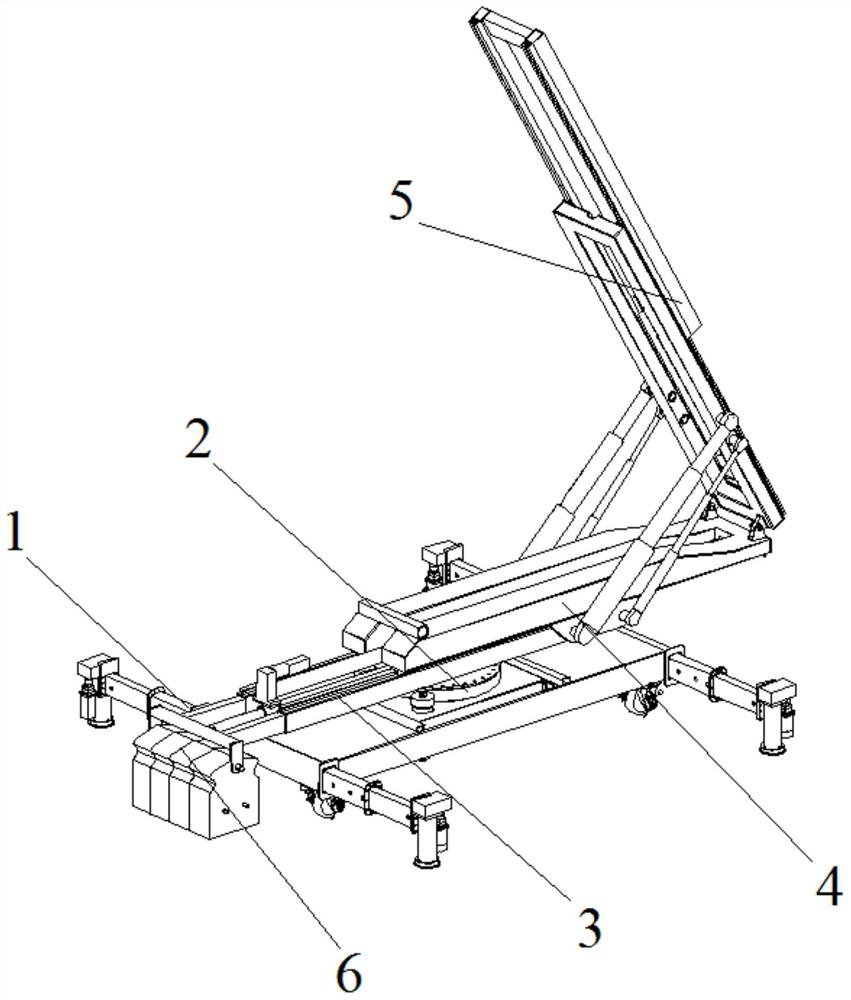
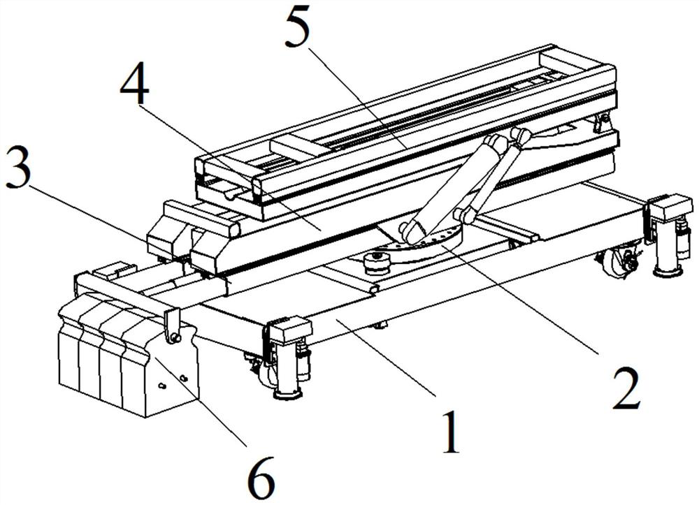
[0040] Specific implementation mode one: refer to Figure 1 to Figure 8 Describe this embodiment. This embodiment provides a layer-moving type large-stroke six-degree-of-freedom heavy-duty installation vehicle. The heavy-duty installation vehicle includes a chassis system 1, a rotary system 2, a No. 1 feed platform 3, a vertical turning System 4, the No. 2 feed platform 5 and the mobile counterweight system 6; the slewing system 2 is embedded in the middle of the chassis system 1, and the slewing system 2 is slidably connected with the chassis system 1, and the No. 1 feed platform 3 is set on the slewing system 2 , and the No. 1 feeding platform 3 is fixedly connected with the slewing system 2. The slewing system 2 drives the No. 1 feeding platform 3 to rotate on the chassis system 1. The vertical turning system 4 is slidingly connected with the No. 1 feeding platform 3, the No. 2 feeding platform 5 is set on the vertical turning system 4, and the No. 2 feeding platform 5 is s...
specific Embodiment approach 2
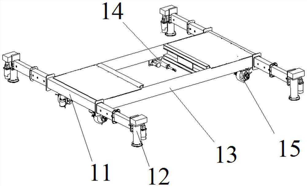
[0042] Specific implementation mode two: refer to Figure 1 to Figure 8 Describe this embodiment. This embodiment is to further limit the chassis system 1 described in Embodiment 1. In this embodiment, the chassis system 1 includes two telescopic beams 11, four lifting legs 12, a vehicle frame Welding body 13, driving electric cylinder 14 and four omnidirectional steering wheels 15, the two telescopic beams 11 are relatively fixed on the two ends of the vehicle frame welding body 13, and the center line of each telescopic beam 11 along the length direction is in line with the The frame welding body 13 is arranged collinearly along the center line in the width direction, and the center of the upper surface of the frame welding body 13 is processed with a rectangular through hole, and a slideway is installed on the inner wall of one end of the rectangular through hole near each telescopic beam 11 , and the two slides are set opposite to each other, the slewing system 2 is set in...
specific Embodiment approach 3
[0045] Specific implementation mode three: refer to Figure 1 to Figure 8 This embodiment is described. This embodiment is to further limit the rotary system 2 described in the second specific embodiment. In this embodiment, the rotary system 2 includes a supporting welding body 21, a rotary bearing 22, two rotating motors 23 and Four pulleys 24, described supporting welding body 21 is arranged in the rectangular through hole, and supporting welding body 21 is equipped with two pulleys 24 towards the side of slideway, and each pulley 24 is embedded on the adjacent slideway, drives motor The power output end of the cylinder 14 is fixedly connected with the outer wall of the supporting welding body 21, and the electric cylinder 14 is driven to drive the supporting welding body 21 to move back and forth on the slideway in the rectangular through hole. hole, the slewing bearing 22 is embedded in the No. 1 through hole, and the fixed ring of the slewing bearing 22 is fixedly connec...
PUM
 Abstract
Description
Claims
Application Information
 - R&D
- Intellectual Property
- Life Sciences
- Materials
- Tech Scout
- Unparalleled Data Quality
- Higher Quality Content
- 60% Fewer Hallucinations
Browse by: Latest US Patents, China's latest patents, Technical Efficacy Thesaurus, Application Domain, Technology Topic, Popular Technical Reports.
© 2025 PatSnap. All rights reserved.Legal|Privacy policy|Modern Slavery Act Transparency Statement|Sitemap|About US| Contact US: help@patsnap.com


