Automatic lifting flood bank for underground garage or subway and using method thereof

An underground garage and automatic lifting technology, applied in door/window applications, war damage prevention, door/window accessories, etc., can solve the problems of large manpower, cost, sandbags or baffles that are prone to collapse, etc., to reduce energy consumption, The effect of increasing buoyancy and increasing the contact area

Inactive Publication Date: 2021-12-07
温州富贾科技有限公司
View PDF0 Cites 2 Cited by
  • Summary
  • Abstract
  • Description
  • Claims
  • Application Information

AI Technical Summary

Problems solved by technology

[0005] In view of this, in order to solve the problem that the current method of using sandbags or baffles to prevent floods from entering garages or subways consumes a lot of manpower and material resources, the anti-flood is not timely, the sandbags or baffles are prone to collapse, and the flood control effect is not good. An automatic lifting flood protection embankment for underground garage or subway and its application method

Method used


Image

  • Automatic lifting flood bank for underground garage or subway and using method thereof
  • Automatic lifting flood bank for underground garage or subway and using method thereof
  • Automatic lifting flood bank for underground garage or subway and using method thereof

Examples


Embodiment 1

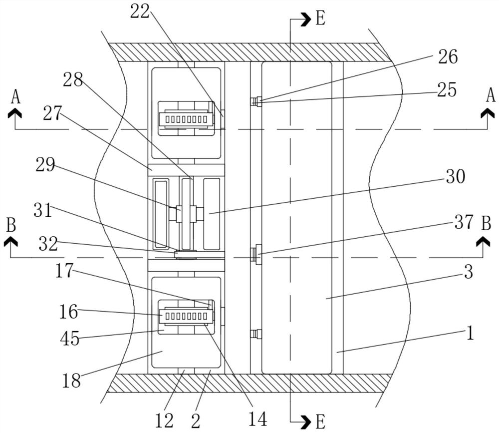
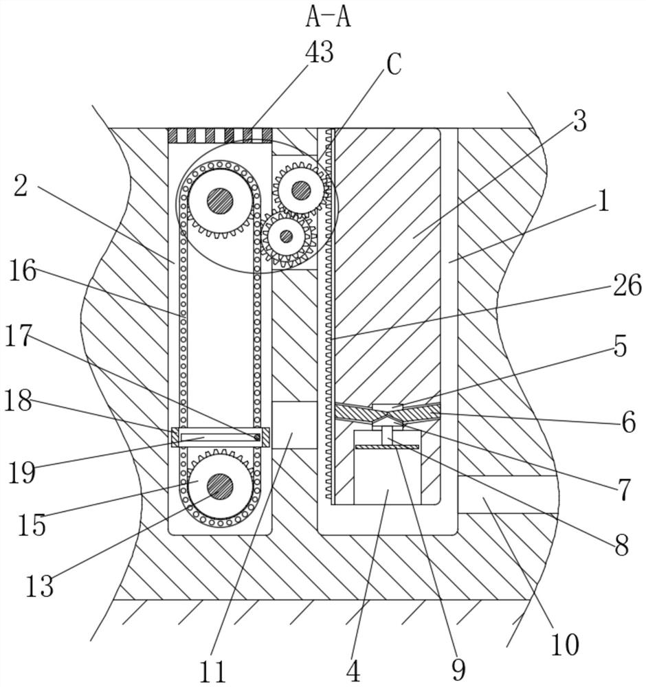
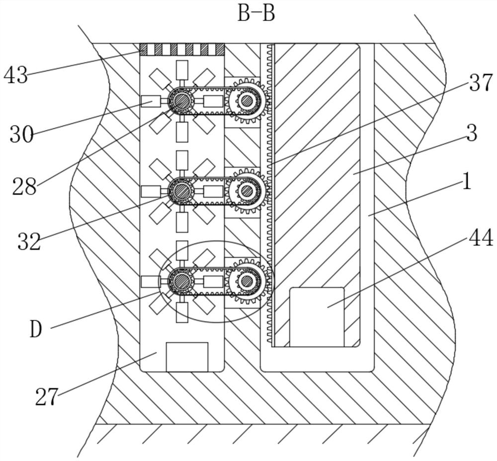
[0044] Such as Figure 1-7 A kind of automatic lifting flood protection embankment for underground garage or subway is shown, including the first chute 1 and the second chute 2 located on the ground, one side inner wall of the first chute 1 is provided with the second chute 2 The first chute 1 is slidably connected with a flood dike 3 through the connected through hole 11, and the flood dike 3 is provided with multiple sets of first buoyancy components for floating the flood dike 3 upwards, and the second chute 2 is fixedly connected There are two symmetrical baffles 27 with rectangular grooves. Two sets of second buoyancy components with the same structure are arranged in the second chute 2. The second buoyancy components are used to drive the flood embankment 3 to slide upwards. The two baffles The sides of the boards 27 close to each other are provided with multiple groups of drive assemblies, the drive assemblies are used to drive the flood embankment 3 to slide upwards, a...

Embodiment 2

[0056] This embodiment is a further improvement of the previous embodiment, such as Figure 1-9 As shown, a kind of automatic lifting flood protection embankment for underground garage or subway, comprises the first chute 1 and the second chute 2 on the ground, one side inner wall of the first chute 1 is provided with the second chute 2 The first chute 1 is slidably connected with a flood dike 3 through the connected through hole 11, and the flood dike 3 is provided with multiple sets of first buoyancy components for floating the flood dike 3 upwards, and the second chute 2 is fixedly connected There are two symmetrical baffles 27 with rectangular grooves. Two sets of second buoyancy components with the same structure are arranged in the second chute 2. The second buoyancy components are used to drive the flood embankment 3 to slide upwards. The two baffles The sides of the boards 27 close to each other are provided with multiple groups of drive assemblies, the drive assemblie...


PUM


Abstract

The invention relates to an automatic lifting flood bank for an underground garage or a subway. The automatic lifting flood bank comprises a first sliding groove and a second sliding groove, wherein the first sliding groove and the second sliding groove are located in the ground, a through hole which communicates with the second sliding groove is formed in the inner wall of one side of the first sliding groove, a flood bank body is slidably connected into the first sliding groove, a plurality of first buoyancy assemblies which are used for enabling the flood bank to float upwards are arranged in the flood bank, two symmetrical baffles with rectangular grooves are fixedly connected into the second sliding groove, two second buoyancy assemblies of the same structure are arranged in the second sliding groove, the second buoyancy assemblies are used for driving the flood bank to slide upwards, a plurality of driving assemblies are arranged on the sides, close to each other, of the two baffles and are used for driving the flood bank to slide upwards, and a drainage hole is formed in the side, away from the second sliding groove, of the first sliding groove. The problems that a large amount of manpower and material resources are consumed, flood fighting is not timely, sandbags or baffles are easy to collapse, and the flood control effect is poor in the existing mode that the sandbags or baffles are used for preventing flood from entering garages or subways are solved.

Description

technical field [0001] The invention belongs to the technical field of flood control, and relates to an automatic lifting flood control embankment for underground garages or subways and a use method thereof. Background technique [0002] With the rapid improvement of people's living standards, the use of vehicles has become more and more popular, and the demand for garages has also increased accordingly. In urban areas with tight land use, in order to reduce the road area occupied by garages, garages are mostly installed underground to form underground garages, and subways are fast, large-capacity, and electric traction rail transit built in cities. The train runs on a fully enclosed line, and the line located in the central city is basically set in an underground tunnel. The subway is a proprietary, high-density, high-capacity urban rail transit system covering various underground and above-ground road rights in urban areas. Taiwan, China The subway calls it "MRT". [000...

Claims


Application Information

Patent Timeline
Patent Type & Authority Applications(China)
IPC IPC(8): E05F1/00E06B5/02E06B5/10
CPCE05F1/006E06B5/025E06B5/10
Inventor 倪赐圭
Owner 温州富贾科技有限公司
Why Eureka
Try Eureka