
Blower

A blower, fan technology, applied in mechanical equipment, machines/engines, liquid fuel engines, etc., can solve the problem of lack of air flow resistance increase, and achieve the effect of reducing flow resistance increase

Active Publication Date: 2021-12-07
LG ELECTRONICS INC
View PDF3 Cites 0 Cited by
  • Summary
  • Abstract
  • Description
  • Claims
  • Application Information

AI Technical Summary

Problems solved by technology

However, the reality is that there is a lack of research on solutions that can reduce the increase in air flow resistance or noise caused by the installation of grilles.

Method used


Image

  • Blower
  • Blower
  • Blower

Examples


Embodiment Construction

[0064] Hereinafter, the embodiments disclosed in this specification will be described in detail with reference to the drawings, and the same or similar structural elements will be assigned the same reference numerals regardless of the reference numerals, and repeated descriptions thereof will be omitted.

[0065] In the process of describing the embodiments disclosed in this specification, if it is judged that the specific description of related known technologies obscures the gist of the embodiments disclosed in this specification, the detailed description will be omitted. Moreover, the attached drawings are only for easy understanding of the embodiments disclosed in this specification, and the technical ideas disclosed in this specification are not limited by the attached drawings, but should be understood as covering the ideas of the present invention and all changes, equivalents and even substitutes falling within the scope of protection.

[0066] Terms including ordinal n...


PUM


Abstract

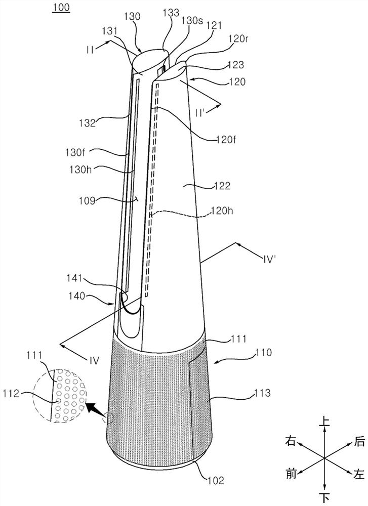
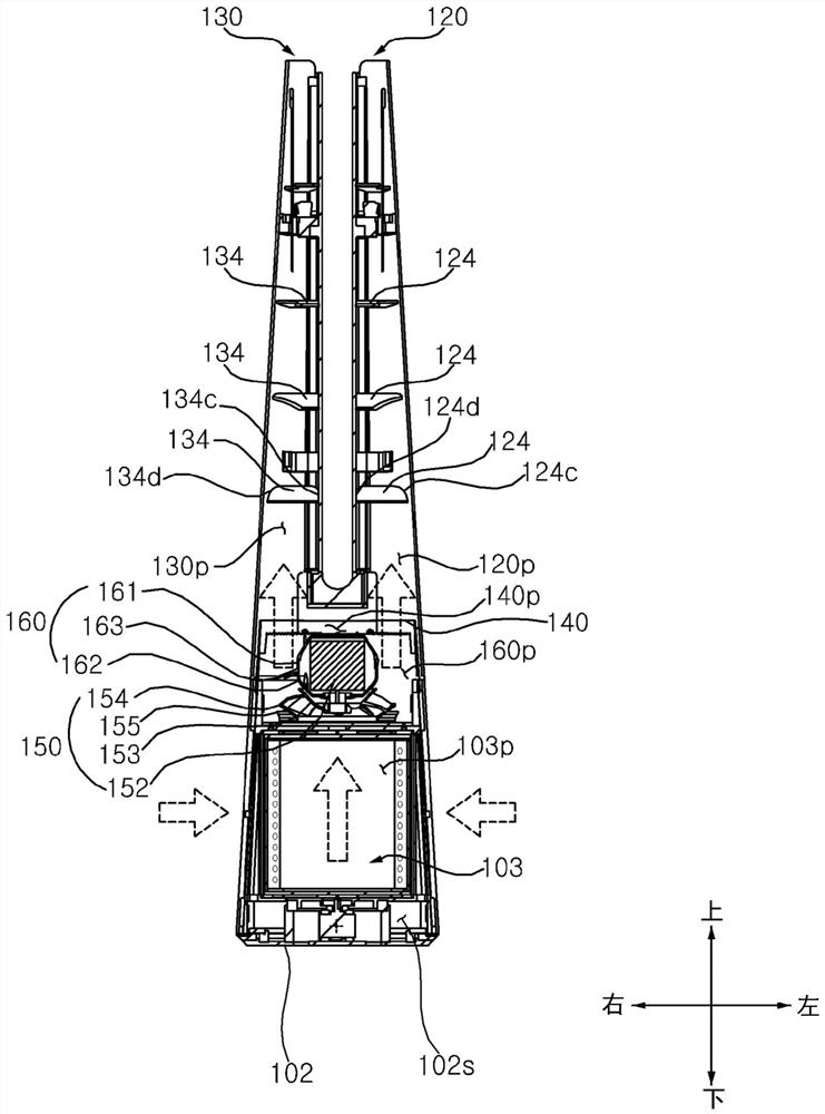
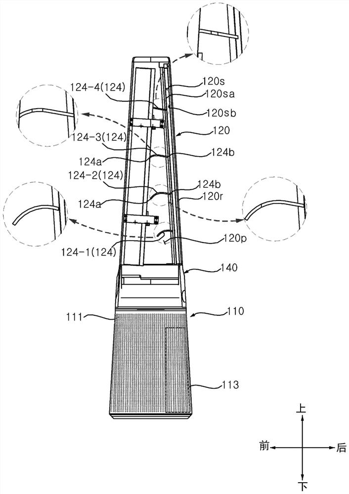
A blower is provided. The blower of the present disclosure includes: a lower body having a suction hole through which air passes; a fan disposed inside the lower body, and causing a flow of air; and a filter disposed inside the lower body, positioned upstream of the fan, and which extends long in a longitudinal direction of the lower body, wherein a longitudinal axis of the filter is biased with respect to a longitudinal axis of the lower body.

Description

technical field [0001] The present invention relates to blowers. In particular, the present invention relates to a blower provided with an air-purifying filter. Background technique [0002] Blowers can be used to circulate air in an indoor space or create airflow towards users by creating a flow of air. In recent years, studies have been made on the air discharge structure of the blower that can provide comfort to the user. [0003] Regarding this, Korean authorized patents KR2011-0099318 and KR2020-0085846 disclose an air supply device and a fan for blowing air using the Coanda effect. [0004] On the other hand, conventional air blowers are provided with filters for air purification. However, the reality is that there is a lack of research on the scheme of maximizing the volume of the filter in the space where the filter is installed. [0005] In addition, the conventional air blower proposes a grille as a configuration for blocking the user's fingers from entering th...

Claims


Application Information

Patent Timeline
Patent Type & Authority Applications(China)
IPC IPC(8): F04F5/16F04F5/44F04D29/70F04D25/08F04D29/60
CPCF04F5/16F04F5/44F04D29/703F04D25/08F04D29/601F24F1/01F24F2221/28F24F8/80F04D29/626F24F13/28F04D29/441
Inventor 郑载赫崔硕浩朴亨镐金厚辰千仁范李昌勋金柱贤金容民崔致英
Owner LG ELECTRONICS INC
Learn More