Eureka AIR delivers breakthrough ideas for toughest innovation challenges, trusted by R&D personnel around the world.

Self-parallel rolling linear guide rail

A linear guide, guide rail technology, applied in the direction of linear motion bearings, bearings, shafts and bearings, can solve problems such as poor installation accuracy guide rail pair life, waste of resources, guide rail pair damage, etc., and achieve the effect of solving poor installation accuracy.

Pending Publication Date: 2021-12-07
NANJING TECHN EQUIP MFG
View PDF0 Cites 1 Cited by
  • Summary
  • Abstract
  • Description
  • Claims
  • Application Information

AI Technical Summary

Problems solved by technology

[0003] 1) In order to save costs, the installation conditions are seriously bad, and the parallelism of the guide rail pair is seriously out of tolerance. Since the rolling linear guide rail pair only has a degree of freedom in the direction in which the slider runs, it will bring huge internal force to the guide rail pair, and even the guide rail pair will instantly damage
[0004] 2) A high-precision installation foundation was produced at a huge cost, and it was transferred to meet the installation requirements at a certain cost, and finally ensured the service life of the guide rail pair, but the running accuracy after debugging far exceeded the design requirements of the equipment, resulting in certain waste of resources
[0005] Therefore, a self-parallel guide rail pair was invented. The self-parallel linear guide rail pair can be used together with the traditional rolling linear guide rail pair to solve the life problem of the guide rail pair caused by the poor installation accuracy of the traditional rolling linear guide rail pair.

Method used


Image

  • Self-parallel rolling linear guide rail
  • Self-parallel rolling linear guide rail
  • Self-parallel rolling linear guide rail

Examples


Embodiment Construction

[0017] The present invention will be further described below in conjunction with the accompanying drawings.

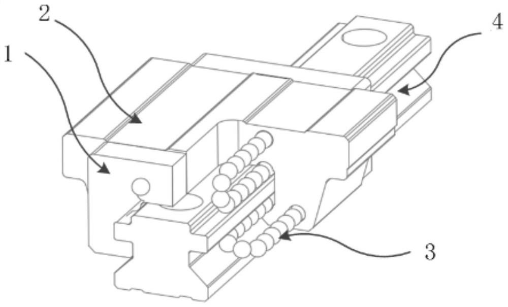
[0018] like figure 1 and figure 2 , a self-parallel rolling linear guide rail of the present invention, including a reverser 1, a slider 2, a guide rail 4 and a rolling line 3 composed of several steel balls, the slider 2 is slidably connected to the guide rail 4, and two reversers 1 is fixed on the front and rear sides of the slider 2, and the rolling line 3 rolls between the slider 2 and the guide rail 4, and realizes circular reciprocating motion through the reverser 1.

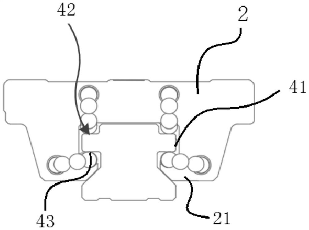
[0019] Two rectangular bosses 41 are symmetrically arranged on the left and right side walls of the guide rail 4, and the first right angle surface 42 is formed between the upper end surface of the rectangular boss 41 and the side wall of the guide rail 4, and the lower end surface of the rectangular boss 41 and the guide rail 4 The second right-angled surface 43 is formed between the side walls...


PUM


Abstract

The invention discloses a self-parallel rolling linear guide rail. A sliding block is connected to the guide rail in a sliding mode, two returners are fixed to the front side and the rear side of the sliding block, four sets of rolling lines roll between the sliding block and the guide rail, circulating reciprocating motion is achieved through the returners, two rectangular bosses are symmetrically arranged on the left side wall and the right side wall of the guide rail, a first right-angle face is formed between the upper end face of each rectangular boss and the side wall of the guide rail, a second right-angle face is formed between the lower end face of each rectangular boss and the side wall of the guide rail, the two sets of rolling lines pass through the first right-angle faces on the two sides of the guide rail when doing the circulating reciprocating motion, and the other two sets of rolling lines pass through second right-angle surfaces on two sides of the guide rail. The self-parallel linear guide rail pair and a traditional rolling linear guide rail pair are used together, so that the problem of service life of the guide rail pair caused by poor mounting precision of the traditional rolling linear guide rail pair can be solved.

Description

Technical field: [0001] The invention relates to a self-parallel rolling linear guide rail. Background technique: [0002] With the increasing application of guide rail pairs, rolling guide rail pairs are also used in many occasions that do not require high precision, mainly due to two situations: [0003] 1) In order to save costs, the installation conditions are seriously poor, and the parallelism of the guide rail pair is seriously out of tolerance. Since the rolling linear guide rail pair only has a degree of freedom in the direction in which the slider runs, it will bring huge internal force to the guide rail pair, and even the guide rail pair will instantly damage. [0004] 2) A high-precision installation foundation was produced at a huge cost, and it was transferred to meet the installation requirements at a certain cost, and finally ensured the service life of the guide rail pair, but the running accuracy after debugging far exceeded the design requirements of the ...

Claims


Application Information

Patent Timeline
Patent Type & Authority Applications(China)
IPC IPC(8): F16C29/06
CPCF16C29/0659F16C29/0671
Inventor 王守珏殷玲香杨海保
Owner NANJING TECHN EQUIP MFG
Why Eureka
Eureka Blog
Learn More