

Ballast circuit
A circuit and ballast technology, applied in the field of ballast circuits, can solve the problems of lamps not operating alone, mismatching, harmful effects of work, etc.
- Summary
- Abstract
- Description
- Claims
- Application Information
AI Technical Summary
Problems solved by technology
Method used
Image


Examples
Embodiment Construction
[0020] The drawings show preferred embodiments of the invention. In this preferred embodiment, n=2. The same parts and elements in the figures are designated by the same numerals and letters, have the same structure and the same operation.
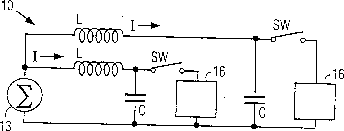
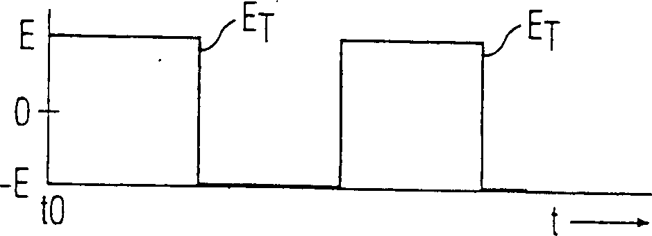
[0021] see figure 1 , 2(G), 2(b) and 2(c), the ballast output circuit 10 includes at least two series-connected devices of an inductor L and a capacitor C connected to both ends of the square wave generator 13. Square wave generator 13 is preferably, but not limited to, a half-bridge inverter generating voltage E (ie, the output voltage of the inverter). A lamp load 16 is connected across each capacitor C through a switch SW. The switch SW is only for displaying the pre-ignition and ignition status of the simulated lamp. The current I flowing through each inductor L includes a fundamental frequency component If1 and a third harmonic component I3f1 of the fundamental frequency. Other currents with higher odd harmonics are present, but ...
PUM
 Abstract
Description
Claims
Application Information