
Intelligent distribution transformer

A technology for distribution transformers and intelligent power distribution, which is applied in the field of distribution transformers, can solve problems such as shortening, temperature rise of distribution transformers, and impact on service life of distribution transformers, so as to ensure service life, speed up circulation, and improve service life Effect

Pending Publication Date: 2021-12-07
莫朗(江苏)电气有限公司
View PDF0 Cites 3 Cited by
  • Summary
  • Abstract
  • Description
  • Claims
  • Application Information

AI Technical Summary

Problems solved by technology

[0003] The operating temperature of the distribution transformer has a great relationship with its service life. The operation of the transformer below 95°C belongs to the normal operating temperature range, and its theoretical service life is 20 years; if it is operated at 110°C, the service life will be shortened to 7 years; if When the temperature rises to 130°C, its service life will be shortened to 2 years; and when the transformer continues to operate at a temperature of 170°C, it is expected to be scrapped in about a day
[0004] However, the current distribution transformers are mostly installed outdoors on the pole or on the platform, and the installation requirements should be no less than 2.5 meters from the ground, which causes the distribution transformers to receive sunlight for a long time when they are working. The temperature of the distribution transformer rises sharply, which has a serious impact on the service life of the distribution transformer. Therefore, it is necessary to design an intelligent distribution transformer to solve this problem.

Method used


Image

  • Intelligent distribution transformer
  • Intelligent distribution transformer
  • Intelligent distribution transformer

Examples


Embodiment Construction

[0031] Next, the technical solutions in the embodiments of the present invention will be described in the following examples in the embodiments of the present invention, and it is clearly, and it is merely the embodiments of the present invention, not all embodiments; Embodiments in the present invention, those of ordinary skill in the art are in the range of protection of the present invention without making creative labor.

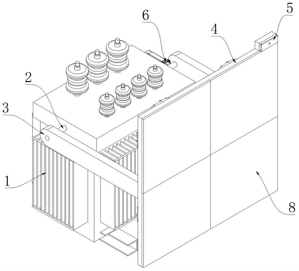
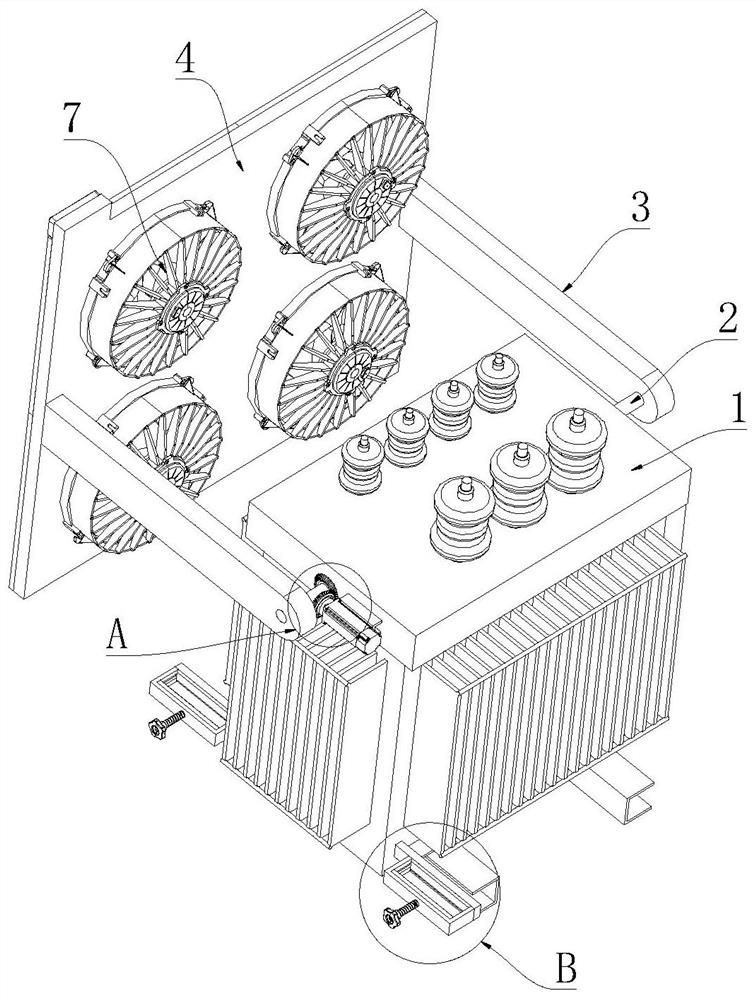
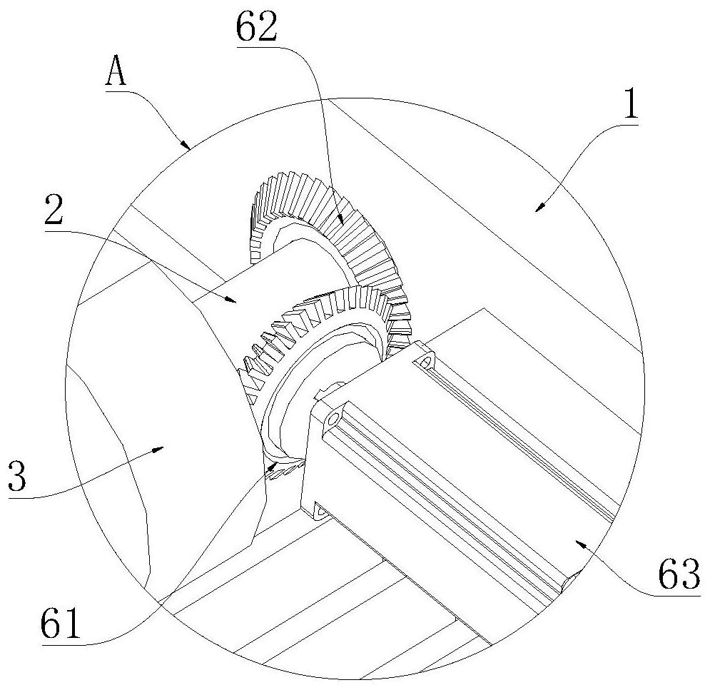
[0032] See Figure 1-7 The intelligent distribution transformer provided in this specific embodiment includes a distribution transformer body 1, and the top portion of the distribution transformer body 1 is inserted with a horizontally rotating shaft 2 by a bearing direction, and both sides of the rotation shaft 2 extends respectively. The exterior of the power distribution transformer body 1; the baffle 4, both sides of the baffle 4 are fixedly connected to the billed rod 3, and the two sides of the two struts 3 away from the baffle 4 are fixed to both sides...


PUM


Abstract

The invention relates to the technical field of distribution transformers, and discloses an intelligent distribution transformer. The transformer comprises a distribution transformer body, wherein the top of the distribution transformer body is rotatably inserted with a horizontal rotating shaft through a bearing, and the two sides of the rotating shaft extend to the outside of the distribution transformer body respectively; a baffle, wherein supporting rods are fixedly connected to the two sides of the baffle, the sides, away from the baffle, of the two supporting rods are fixedly connected to the two sides of the rotating shaft correspondingly, and the baffle is used for shielding sunlight irradiating the surface of the distribution transformer body; and a light sensor which is installed on the side, away from the distribution transformer body, of the baffle and used for monitoring the sunlight irradiation direction. Through the arrangement of the driving mechanism, the side, away from the distribution transformer body, of the baffle can face the sun all the time and rotate along with movement of the sun, so that the effect of shielding sunlight is achieved, and the surface of the distribution transformer body is prevented from being exposed to the sun.

Description

Technical field [0001] The present invention belongs to the technical field of power distribution transformers, in particular a smart distribution transformer. Background technique [0002] The power distribution power transformer is a stationary electrical device that is a voltage (current) of a voltage (current) having a different value of AC voltage (stream) to become the same frequency. When the winding is converted at an alternating current, an alternating magnetic flux is generated by a core magnetically magnetically promoted, an alternating electromotive force is in the secondary winding. The high and low of the secondary induction electromotive force is related to the number of turns of the first winding, that is, the voltage magnitude is proportional to the number of turns. The main role is to transmit power, so the rated capacity is its main parameters. The rated capacity is a conventional value of the power, which is characterized by the size of the transmission electr...

Claims


Application Information

Patent Timeline
Patent Type & Authority Applications(China)
IPC IPC(8): H01F27/02H01F27/08G01J1/00H02S20/32F24S30/425
CPCH01F27/02H01F27/085G01J1/00H02S20/32F24S30/425F24S2030/134Y02E10/47Y02E10/50
Inventor 杨利民
Owner 莫朗(江苏)电气有限公司
Learn More