Eureka AIR delivers breakthrough ideas for toughest innovation challenges, trusted by R&D personnel around the world.

Power control method and device for cognitive radio network

A cognitive radio and power control technology, applied in the field of radio networks, can solve problems such as inappropriate influence, system performance degradation, and inability to obtain real-time and accurate descriptions

Pending Publication Date: 2021-12-07
JILIN INST OF CHEM TECH
View PDF0 Cites 0 Cited by
  • Summary
  • Abstract
  • Description
  • Claims
  • Application Information

AI Technical Summary

Problems solved by technology

However, updating the system status of users in the next time slot in the previous time slot based on the power control of the above method in the underlay cognitive network cannot be accurately described in real time
[0004] Furthermore, the limitation of interference temperature is a key constraint to achieve power control in underlying cognitive radio networks, and it is also an important factor to limit dynamic multiplexing and improve spectral efficiency
However, in the above algorithm, the fixed interference temperature threshold is obviously inappropriate for describing the impact of the secondary user on the primary user
At the same time, the actual channel state information is inevitably affected by quantization error, measurement error and uncertain interference, which leads to the degradation of system performance
[0005] Up to now, the power control methods have not included the influence of interference temperature, quantization error, measurement error and uncertain interference into the power control, and there is no good solution to solve the above problems.

Method used

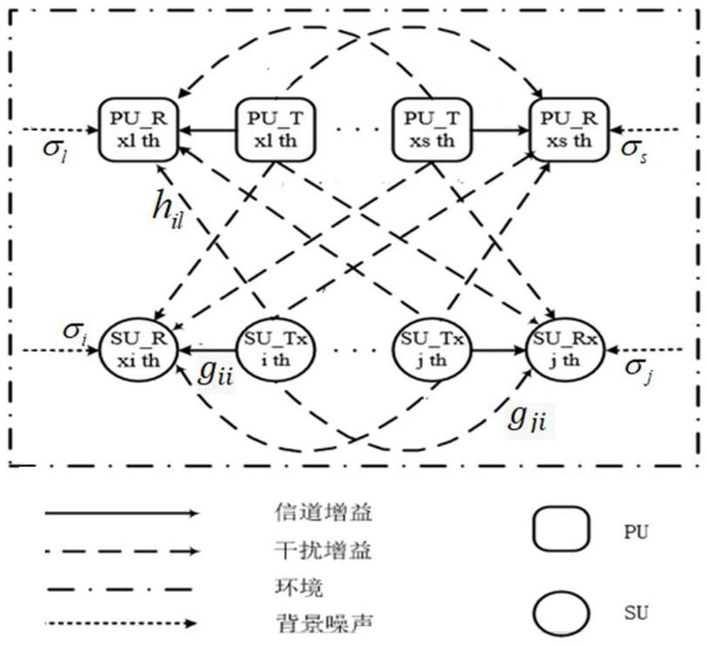
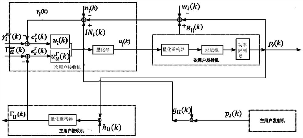
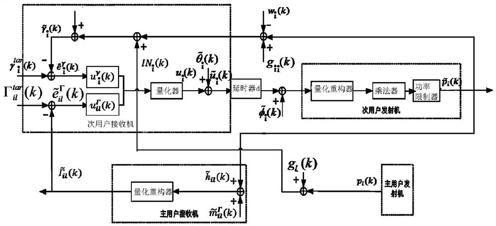

Image

  • Power control method and device for cognitive radio network
  • Power control method and device for cognitive radio network
  • Power control method and device for cognitive radio network

Examples


Embodiment Construction

[0130] Embodiments of the present invention will be described below with reference to the accompanying drawings. Those skilled in the art would recognize that the described embodiments can be modified in various ways or combinations thereof without departing from the spirit and scope of the invention. Accordingly, the drawings and description are illustrative in nature and not intended to limit the scope of the claims. Also, in this specification, the drawings are not drawn to scale, and like reference numerals denote like parts.

[0131] This embodiment provides a power control method for a cognitive radio network, including:

[0132] Step 1. Build a controller with secondary user SNR feedback and secondary user to primary user interference feedback controller A state-space model of error tracking.

[0133] The state space model is as follows:

[0134]

[0135] Among them, k represents the time slot;

[0136] K represents the state feedback gain;

[0137] A,B,B 1...


PUM


Abstract

The invention discloses a power control method and device for a cognitive radio network, wherein the method comprises the steps of constructing a state space model, and calculating a state feedback gain for the state space model through an LMI method; by updating the transmitting power of a secondary user i in a time slot k, the actual measurement signal-to-noise ratio of the secondary user i in the time slot k and the interference of the secondary user i in the time slot k to a primary user l, calculating a secondary user signal-to-noise ratio tracking error in the time slot k and an interference temperature tracking error in the time slot k by combining an error dynamic equation, and selecting a controller according to the positive and negative values, reducing the transmitting power of the secondary user through the controller, controlling the updating instruction according to the fact that the product of the state feedback gain and the input vector of the time slot k is equal to the updating power of the secondary user i, and returning to update again until the transmitting signal of the secondary user does not occupy the frequency spectrum. According to the method, the influence of factors such as near-far effect, fast channel fading, measurement error, multi-access interference and link time delay is considered, and good robust tracking performance is presented through secondary user power control.

Description

technical field [0001] The present invention relates to the technical field of radio networks, in particular to a power control method and device for a cognitive radio network. Background technique [0002] In recent years, with the rapid development of modern wireless communication technology services, limited spectrum resources can no longer meet the growing needs of people. Effectively improving spectrum utilization has become an important topic in the communication field. Cognitive radio can independently search for free spectrum, which can improve the utilization efficiency of spectrum to a certain extent. Compared with existing communication systems (4G, 4.5G), secondary users (SU) and primary users (PU) share licensed frequency bands in underlay cognitive radio networks (CRNs) to improve spectrum utilization. At the same time, this method can be directly built on the mobile wireless network, thereby saving construction costs and reducing network investment. Therefo...

Claims


Application Information

Patent Timeline
IPC IPC(8): H04W52/18H04B17/382
CPCH04W52/18H04B17/382Y02D30/70
Inventor 陈玲玲高兴泉姜德龙艾学忠孟亚男林琳郭帅飞
Owner JILIN INST OF CHEM TECH
Why Eureka
Eureka Blog
Learn More