
Steel tube end plate welding machine

A welding machine and steel pipe technology, applied in the field of machine tools, can solve the problems of high processing cost, low welding quality, low welding qualification rate, etc., and achieve the effects of improving welding processing efficiency, reducing welding processing cost and high degree of automation

Pending Publication Date: 2021-12-10
台州市圣西亚金刚石设备有限公司
View PDF6 Cites 0 Cited by
  • Summary
  • Abstract
  • Description
  • Claims
  • Application Information

AI Technical Summary

Problems solved by technology

Steel pipes usually have bending deformation in the axial direction, which makes the accuracy of parts clamping and positioning low, that is, there is a deviation in the position of the end face of the parts, and the moving track of the welding head is fixed during automatic welding, which leads to the actual welding seam and the welding head. The matching degree of moving trajectory is low, so that there are problems such as low welding quality and low welding qualification rate in the welding of steel pipe end plates
[0003] Taking the heat dissipation pipe in the heating equipment as an example, the end plate of the heat dissipation pipe needs to be sealed after welding to avoid water leakage, that is, the welding requirements of the end plate of the heat dissipation pipe are relatively high, and the current automatic welding equipment cannot guarantee the integrity of the heat dissipation pipe. Quality requirements; thus manual welding of the end plate of the heat pipe has the problems of low production efficiency, high labor intensity and high processing cost

Method used


Image

  • Steel tube end plate welding machine
  • Steel tube end plate welding machine
  • Steel tube end plate welding machine

Examples


Embodiment 1

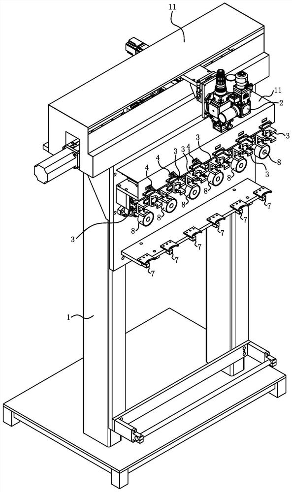
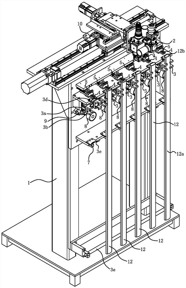
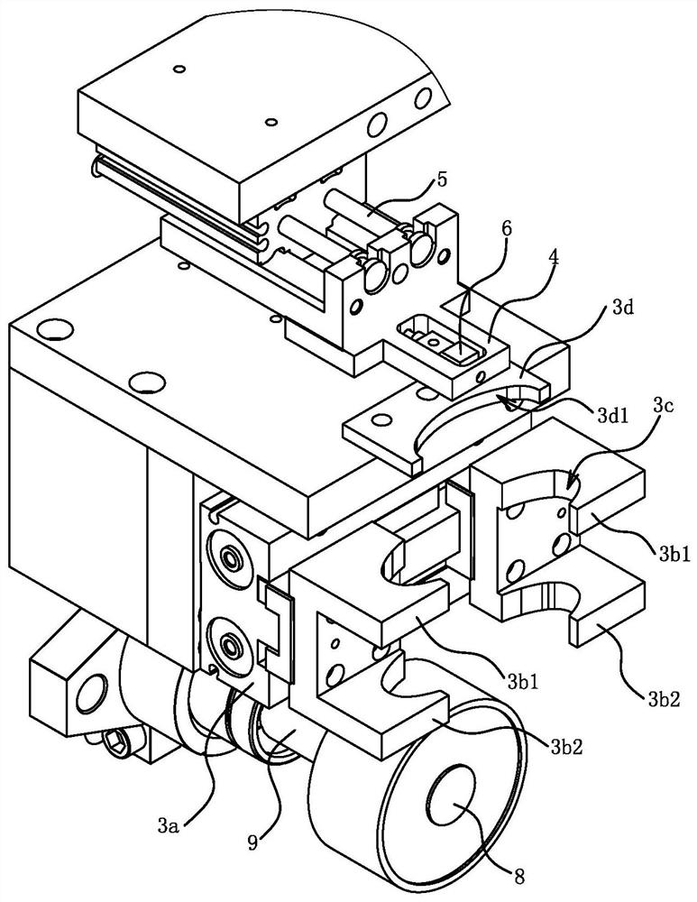
[0024] Embodiment one: if Figure 1 to Figure 4 As shown, a steel pipe end plate welding machine includes a frame 1 , a set of welding operation components 2 , multiple sets of clamping and positioning components 3 and a plurality of top surface positioning backers 4 .

[0025] The steel pipe 12 includes a pipe body 12a and an end plate 12b. The steel pipe end plate welding machine clamps and positions the pipe body 12a first, and then welds the end plate 12b to the pipe body 12a. The number of clamping and positioning components 3 is the same as the number of top positioning backers 4, and the clamping and positioning components 3 and the top positioning backers 4 are set in one-to-one correspondence, thus forming a plurality of welding stations, and the plurality of welding stations are relative to the frame 1 Arranged left and right; multiple processes such as installing the steel pipe 12, removing the steel pipe 12 and welding the steel pipe 12 can be carried out at the sa...

Embodiment 2

[0039] Embodiment 2: The structure and principle of this embodiment are basically the same as those of Embodiment 1. The basic similarities will not be described redundantly, and only the differences will be described. The difference lies in: the clamping and positioning assembly 3 includes a rear positioning backer And the front side pressure head, the rear side positioning backer is fixed on the frame 1, and the rear side positioning backer is provided with a positioning groove matching with the steel pipe profile, and the cylinder connected to the front side pressure head is installed on the frame 1. When the steel pipe is embedded in the positioning groove and the piston rod of the cylinder retracts, the front pressure head can press the steel pipe on the rear positioning backer.


PUM


Abstract

The invention provides a steel tube end plate welding machine, and belongs to the technical field of machinery. The problem that an existing welding machine is insufficient in steel tube clamping and positioning precision is solved. The steel tube end plate welding machine comprises a rack, wherein a clamping and positioning assembly used for clamping and positioning the top of a steel tube is installed on the rack, a welding operation assembly and a top face positioning backer used for positioning the top face of the steel tube are arranged above the clamping and positioning assembly, and the top face positioning backer is connected with the rack through a driving element; the driving element can enable a top face positioning backer to avoid the area over the steel tube clamped by the clamping and positioning assembly. The clamping and positioning assembly clamps the top of the steel tube, so that the distance between the clamped and positioned part of the steel tube and the top face is small, the influence of bending deformation of the steel tube on the clamping precision is reduced, and the clamping and positioning precision of the end of the steel tube is improved. The positioning mode of the steel tube end plate welding machine is suitable for clamping and positioning steel tubes with different lengths, the positions of the upper ends of the steel tubes are consistent, and the steel tube end plate welding machine has the advantages of flexible machining and high machining efficiency.

Description

technical field [0001] The invention belongs to the technical field of machine tools, and relates to a welding machine, in particular to a steel pipe end plate welding machine. Background technique [0002] A steel pipe is a steel material with a hollow section whose length is much greater than its diameter or circumference. Steel pipes are used in a wide range of applications, such as furniture, heating equipment, etc. When steel pipes are used, they usually need to be cut according to a set length and end plates are used to cover the ports of the steel pipes. Steel pipes usually have bending deformation in the axial direction, which makes the precision of parts clamping and positioning low, that is, there is a deviation in the position of the end face of the parts. The matching degree of the moving trajectory is low, so that there are problems such as low welding quality and low welding qualification rate in the welding of steel pipe end plates. [0003] Taking the heat ...

Claims


Application Information

Patent Timeline
IPC IPC(8): B23K26/21B23K26/70
CPCB23K26/21B23K26/702Y02P70/10
Inventor 项大清
Owner 台州市圣西亚金刚石设备有限公司
Learn More